VP536E View Datasheet(PDF) - Zarlink Semiconductor Inc
Part Name
Description
View to exact match
VP536E Datasheet PDF : 14 Pages
| |||
VP536E
NTSC/PAL Video Standards
Both NTSC (4-field, 525 lines) and PAL (8-field, 625
lines) video standards are supported by the VP536E. All
raster synchronization, color subcarrier and burst
characteristics are adapted to the standard selected.
However, different input clock frequencies are necessary for
each of the two video standards. For the NTSC mode of
operation, input clock frequencies of 25.048948MHz. and
12.524474MHz. are required. For the PAL mode of
operation, the required input clock frequencies are
29.500000MHz. and 14.750000MHz. The two input clock
frequencies in each of the video standards are related by a
ratio of 2.
The mode of operation is selected through the CTRLB1
and CTRLB2 pins as shown in Table 1.
Progressive Scan Display
Progressive scan (non-interlaced fields) display mode is
available for semi-NTSC and semi-PAL video applications.
For NTSC, there are 263 lines in each field instead of
262.5 lines per field in a normal NTSC display. Thus, 263
lines of field 2 data are scanned as field 1 resulting in 526
lines per ‘frame’.
For PAL, there are 313 lines in each field instead of
312.5 lines per field in a normal PAL display. Thus, 313 lines
of field 2 data are scanned as field 1, resulting in 626 lines
per ‘frame’.
Progressive scanning display mode is selected through
the CTRLB1 and CTRLB2 pins as shown in Table 1.
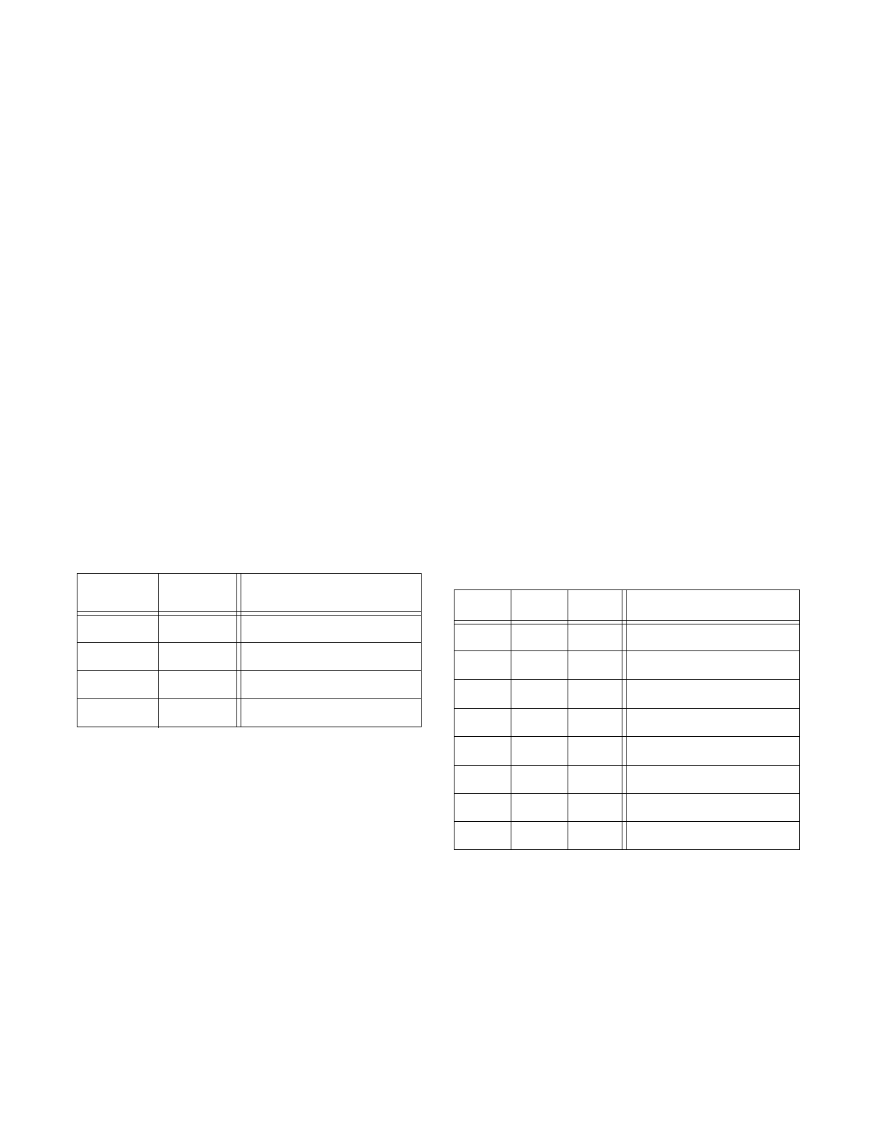
Table 1: VP536E Modes of Operation
CTRLB2 CTRLB1
Video Standard
0
0
NTSC
0
1
Progressive Scan NTSC
1
0
PAL
1
1
Progressive Scan PAL
NOTE: CTRLB1 & CTRLB2 are internally pulled low, therefore, if left
unconnected, NTSC is the default mode of operation.
Video Timing
The VP536E has an internal sync generator which
produces video timing signals appropriate to the mode of
operation. All timing signals are derived from the two input
clocks. These clocks are input on the CLK25I pin
(25.048948MHz:NTSC/29.5MHz:PAL) and the CLK12I pin
(12.52444MHz:NTSC/14.75MHz:PAL). The two input clock
frequencies for NTSC and PAL are related by a ratio of 2.
The lower frequency corresponds to the input pixel data
rate. Input pixel data is latched in on the rising edge of the
CLK12I clock.
The clocks must be derived from a crystal controlled
oscillator in order to avoid timing, chroma frequency and
modulation errors.
The video timing generator produces the internal
composite sync, blanking and burst gate as well as
externally available horizontal sync (HS) and vertical sync
(VS) pulse signals. The HS and VS signals are negative true
pulses coincident with the sync pulses in the output video
signals.
The HS signal has the same duration as a standard
horizontal sync pulse but is continuous through the vertical
sync interval.
Input Pixel Data Format
Input pixel data may be in one of two formats; pre-
gamma corrected RGB and YUV. This format is controlled by
the state of theCTRLA1, CTRLA2 and CTRLA3 pins as
shown in Table 2.
The RGB input data coding is straight binary and is in
the range of 0-255. In the YUV input mode, Y, U and V data is
presented on the R, B and G input data buses, respectively.
Y data coding is binary and is in the range of 0-247. U and V
coding is in two’s compliment binary. U is in the range of -
102 to +102 and V is in the range of -107 to +107.
Dithering
In applications where the input RGB/YUV data has
been subject to video compression, visual artefacts may
occur in the video display depending on the type and quality
of video compression employed.
The VP536E incorporates dithering techniques on the
incoming RGB data and on the internal luminance data in
order to minimize any artefacts.
Each of these dithering techniques can be enabled or
disabled through the CTRLA1 and CTRLA2 pins as shown in
Table 2 below.
Table 2: Input Pixel Data Format and Dithering Selection
CTRLA3 CTRLA2 CTRLA1 Input Pixel Data Format
0
0
0
RGB input dither ON, Luma
dither OFF
0
0
1
RGB input dither ON, Luma
dither ON
0
1
0
RGB input dither OFF, Luma
dither ON
0
1
1
RGB input dither OFF, Luma
dither OFF
1
0
0
YUV input, Luma dither ON
1
0
1 YUV input, Luma dither OFF
1
1
0
reserved
1
1
1
reserved
NOTE: CTRLA1 is internally pulled high, while CTRLA2 & CTRLA3
are internally pulled low; therefore if left unconnected, pre-gamma
corrected RGB is the default input pixel data format with input RGB
and luma dithering enabled.
Video Blanking
The VP536E automatically performs standard
composite video blanking. Lines 1-17, 261-279, 523-525
inclusive, as well as the last half of line 260 and the first half
of line 280 are blanked in the NTSC mode. In PAL mode,
lines 1-22, 311-335, 624-625 inclusive, as well as the last
half of line 623 and the first half of line 23 are blanked.
2
Share Link: 