VV5409C001 View Datasheet(PDF) - Vision
Part Name
Description
View to exact match
VV5409C001 Datasheet PDF : 39 Pages
| |||
VV5409 CMOS Monochrome Sensor Datasheet (Restricted) Rev 1.0
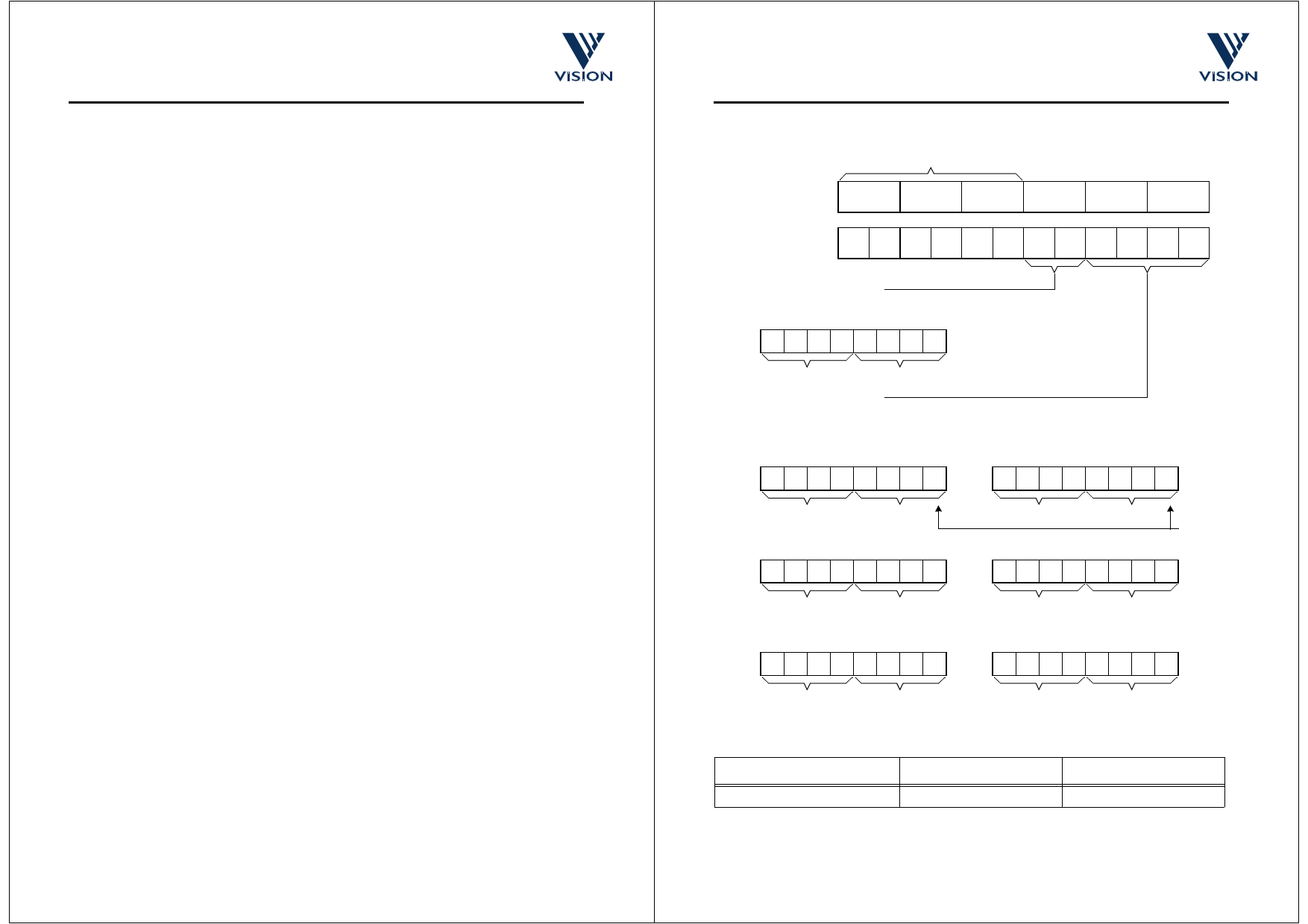
5.2 Embedded control data
To distinguish the control data from the sampled video data all control data is encapsulated in embedded
control sequences. These are 6 bytes long and include a combined escape/sync character, 1 control byte
(the ‘command byte’) and 2 bytes of supplementary data.
To minimise the susceptibility of the embedded control data to random bit errors redundant coding
techniques have been used to allow single bit errors in the embedded control words to be corrected.
However, more serious corruption of control words or the corruption of escape/sync characters cannot be
tolerated without loss of sync to the data stream. To ensure that a loss of sync is detected a simple set of
rules has been devised. The four exceptions to the rules are outlined below:
1. Data containing a command words that has two bit errors.
2. Data containing two ‘end of line’ codes that are not separated by a ‘start of line’ code.
3. Data preceding an ‘end of field’ code before a start of frame’ code has been received.
4. Data containing line that do not have sequential line numbers (excluding the ‘end of field’ line).
If the video processor detects one of these violations then it should abandon the current field of video
5.2.1 The combined escape and sync character
Each embedded control sequence begins with a combined escape and sync character that is made up of
three words. The first two of these are FFH FFH- constituting two words that are illegal in normal data. The
next word is 00H - guaranteeing a clear signal transition that allows a video processor to determine the
position of the word boundaries in the serial stream of nibbles. Combined escape and sync characters are
always followed by a command byte - making up the four byte minimum embedded control sequence.
5.2.2 The command word
The byte that follows the combined escape/sync characters defines the type of embedded control data. Three
of the 8 bits are used to carry the control information, four are ‘parity bits’ that allow the video processor to
detect and correct a certain level of errors in the transmission of the command words, the remaining bit is
always set to 1 to ensure that the command word is never has the value 00H. The coding scheme used allows
the correction of single bit errors (in the 8-bit sequence) and the detection of 2 bit errors The three data bits
of the command word are interpreted as shown in Figure 5.2.The even parity bits are based on the following
relationships:
1. An even number of ones in the 4-bit sequence (C2, C1, C0 and P0).
2. An even number of ones in the 3-bit sequence (C2, C1, P1).
3. An even number of ones in the 3-bit sequence (C2, C0, P2).
4. An even number of ones in the 3-bit sequence (C1, C0, P3).
Table 5.3 shows how the parity bits maybe used to detect and correct 1-bit errors and detect 2-bit errors.
5.2.3 Supplementary Data
The last 2 bytes of the embedded control sequence contains supplementary data. Three options:
1. The current 12-bit line number. The 12-bit line number is packaged up by splitting it into two 6-bit val-
ues. Each 6-bit values is then converted into an 8-bit value by adding a zero to the start and an odd
word parity bit at the end.
2. If the line code equals the end of line, the 2 bytes are padded out using null characters (FFH).
3. If the line code equals the end of line and digitise analogue input enabled then the 2 supplementary
data bytes contain 2 8-bit values representing the values of the analogue input at those two points in
time.
Commercial In Confidence
cd38041a.fm
08/10/98
15
VV5409 CMOS Monochrome Sensor Datasheet (Restricted) Rev 1.0
8-bit Data
Escape/Sync Sequence
FFH
FFH
00H
XYH D3D2 D1D0
4-wire output
mode
FH FH FH FH 0H 0H XH YH D3 D2 D1 D0
Command (Line Code)
Bit 7 6 5 4 3 2 1 0
1 C2 C1 C0 P3 P2 P1 P0
Nibble XH
Supplementary Data
Nibble YH
(i) Line Number (L11 MSB)
Bit 7 6 5 4 3 2 1 0
0 L11 L10 L9 L8 L7 L6 P
Nibble D3
Nibble D2
or (ii) If Line Code = End of Line then
11111111
Bit 7 6 5 4 3 2 1 0
0 L5 L4 L3 L2 L1 L0 P
Nibble D1
Nibble D0
Odd
word
parity
11111111
Nibble D3 = FH Nibble D2 = FH
Nibble D1 = FH Nibble D0 = FH
or (iii) If Line Code = End of Line and digitise analogue input enabled then
A7 A6 A5 A4 A3 A2 A1 A0
B7 B6 B5 B4 B3 B2 B1 B0
Nibble D3
Nibble D2
Nibble D1
Nibble D0
Figure 5.2 : Embedded Control Sequence
Line Code
End of Line
Nibble XH (1 C2 C1 C0) Nibble YH (P3 P2 P1 P0)
10002 (8H)
00002 (0H)
Table 5.2 : Embedded Line Codes
Commercial In Confidence
cd38041a.fm
08/10/98
16
Share Link: 