VV5409C001 View Datasheet(PDF) - Vision
Part Name
Description
View to exact match
VV5409C001 Datasheet PDF : 39 Pages
| |||
VV5409 CMOS Monochrome Sensor Datasheet (Restricted) Rev 1.0
Gain Binary code Actual signal gain Gain Binary code Actual signal gain
00002
00012
00102
00112
01002
01012
01102
01112
0.500
10002
1.000
10012
0.667
10102
2.000
10112
0.571
11002
1.333
11012
0.800
11102
4.000
11112
Table 4.2 : System Analog Gain Values
0.533
1.143
0.727
2.667
0.615
1.600
0.889
8.000
Clock Divisor Setting
Pixel Clock Divisor
002
2
012
4
102
8
112
16
Table 4.3 : Clock Divisor Values
Commercial In Confidence
cd38041a.fm
08/10/98
13
VV5409 CMOS Monochrome Sensor Datasheet (Restricted) Rev 1.0
5. Digital Video Interface Format
5.1 General description
The video interface consists of a unidirectional, tri-stateable 4-wire data-bus. The nibble transmission is
synchronised to the rising edge of the system clock.
Read-out Order
Progressive Scan (Non-interlaced)
Form of encoding
Uniformly quantised, PCM, 8 bits per sample
Correspondence between video
signal levels and quantisation
levels:
Internally valid pixel-data is clipped to ensure that 00H and FFH
values do not occur when pixel-data is being output on the data-
bus. This gives 254 possible values for each pixel (1 - 254). The
video black level corresponds to code 16.
Table 5.1 : Video encoding parameters
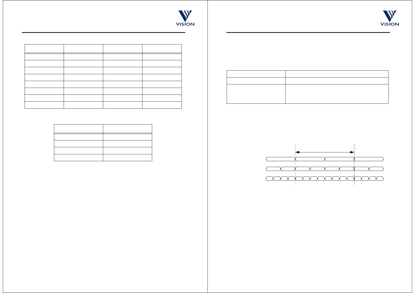
Digital video-data is 8 bits per sample, and can be transmitted in one of three ways:
1. A series pair of 4-bit nibbles, most significant nibble first, on 4-wires
2. Four 2-bit values, most significant 2-bit value first, on 2-wires
3. Bit-serial data, eight 1-bit values, least significant bit first, on 1-wire.
8-bit pixel-data
4 - wire Output Mode
D3,D2,D1,D0
D7,D6,D5,D4
D3,D2,D1,D0
D7,D6,D5,D4
2 - wire Output Mode D3,D2
D1,D0
D7,D6
D5,D4
D3,D2
D1,D0
D7,D6
D5,D4
1 - wire Output Mode D4 D5 D6 D7 D0 D1 D2 D3 D4 D5 D6 D7 D0 D1 D2 D3
Figure 5.1 : 4-wire, 2-wire and 1-wire Output Modes
In the following description the 4-wire mode is used as an example. The 2-wire, and 1-wire modes can be
viewed as variants of the 4-wire mode.
Control information is multiplexed with the sampled pixel-data. Such control information includes both video
timing references, sensor status/configuration data and digitised values for VV5409’s analogue input pin,
AIN.
Video timing reference information takes the form of field start characters, line start characters, end of line
characters and a line counter.
Commercial In Confidence
cd38041a.fm
08/10/98
14
Share Link: 