FSL136MR View Datasheet(PDF) - Fairchild Semiconductor
Part Name
Description
View to exact match
FSL136MR Datasheet PDF : 13 Pages
| |||
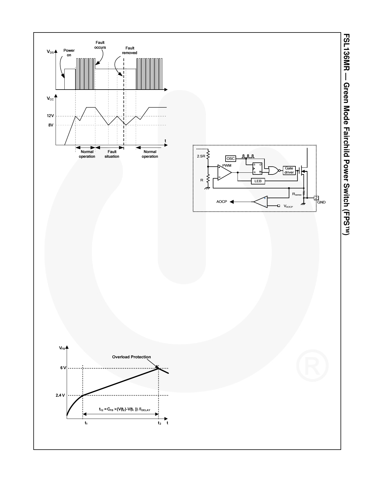
Abnormal Over-Current Protection (AOCP)
When the secondary rectifier diodes or the transformer
pin are shorted, a steep current with extremely high
di/dt can flow through the SenseFET during the LEB
time. Even though the FPS has OLP (Overload
Protection), it is not enough to protect the FPS in that
abnormal case, since severe current stress is imposed
on the SenseFET until OLP triggers. The FPS includes
the internal AOCP (Abnormal Over-Current Protection)
circuit shown in Figure 19. When the gate turn-on signal
is applied to the power SenseFET, the AOCP block is
enabled and monitors the current through the sensing
resistor. The voltage across the resistor is compared
with a preset AOCP level. If the sensing resistor voltage
is greater than the AOCP level, the set signal is applied
to the latch, resulting in the shutdown of the SMPS.
Figure 17. Auto-Restart Protection Waveforms
Overload Protection (OLP)
Overload is defined as the load current exceeding a
pre-set level due to an unexpected event. In this
situation, the protection circuit should be activated to
protect the SMPS. However, even when the SMPS is
operating normally, the overload protection (OLP) circuit
can be activated during the load transition or startup. To
avoid this undesired operation, the OLP circuit is
designed to be activated after a specified time to
determine whether it is a transient situation or a true
overload situation.
In conjunction with the IPK current limit pin (if used), the
current-mode feedback path limits the current in the
SenseFET when the maximum PWM duty cycle is
attained. If the output consumes more than this
maximum power, the output voltage (VO) decreases
below its rating voltage. This reduces the current
through the opto-coupler LED, which also reduces the
opto-coupler transistor current, thus increasing the
feedback voltage (VFB). If VFB exceeds 2.4V, the
feedback input diode is blocked and the 5µA current
source (IDELAY) slowly starts to charge CFB. In this
condition, VFB increases until it reaches 6V, when the
switching operation is terminated, as shown in Figure
18. The shutdown delay is the time required to charge
CFB from 2.4V to 6V with 5µA current source.
Figure 19. Abnormal Over-Current Protection
Thermal Shutdown (TSD)
The SenseFET and the control IC are integrated,
making it easier to detect the temperature of the
SenseFET. When the temperature exceeds
approximately 137°C, thermal shutdown is activated.
Over-Voltage Protection (OVP)
In the event of a malfunction in the secondary-side
feedback circuit or an open feedback loop caused by a
soldering defect, the current through the opto-coupler
transistor becomes almost zero. Then, VFB climbs up in
a similar manner to the overload situation, forcing the
preset maximum current to be supplied to the SMPS
until the overload protection is activated. Because
excess energy is provided to the output, the output
voltage may exceed the rated voltage before the
overload protection is activated, resulting in the
breakdown of the devices in the secondary side. To
prevent this situation, an over-voltage protection (OVP)
circuit is employed. In general, VCC is proportional to the
output voltage and the FPS uses VCC instead of directly
monitoring the output voltage. If VCC exceeds 24V, OVP
circuit is activated, resulting in termination of the
switching operation. To avoid undesired activation of
OVP during normal operation, VCC should be designed
to be below 24V.
Figure 18. Overload Protection (OLP)
© 2009 Fairchild Semiconductor Corporation
FSL136MR • Rev. 1.0.7
Output-Short Protection (OSP)
If the output is shorted, the steep current with extremely
high di/dt can flow through the SenseFET during the
LEB time. Such a steep current brings high-voltage
stress on the drain of SenseFET when turned off. To
protect the device from such an abnormal condition,
OSP detects VFB and SenseFET turn-on time. When the
VFB is higher than 1.6V and the SenseFET turn-on time
www.fairchildsemi.com
10
Share Link: 