VV5409C001 View Datasheet(PDF) - Vision
Part Name
Description
View to exact match
VV5409C001 Datasheet PDF : 39 Pages
| |||
VV5409 CMOS Monochrome Sensor Datasheet (Restricted) Rev 1.0
within the active lines. The pixel data may be separated from the line header and end-of-line control
sequence by a number of ‘blank’ bytes (07H) e.g. when the border lines and pixels are disabled 07H is output
in place of first 2 and last 2 pixels in a valid video line.
5.3.4 Start of frame line timing
The start of frame line which begins each video field contains no video data but instead contains the contents
of all the serial interface registers. This information follows the start-of-line header immediately and is
terminated by an end-of-line control sequence. To ensure that no escape/sync characters appear in the
sensor status/configuration information the code 07H is output after each serial interface value. Thus it takes
256 pixel clock periods (512 system clocks) to output all 128 of the serial interface registers. The remainder
of the 356 pixel periods of the video portion of the line is padded out using 07H values. The first two pixel
locations are also padded with 07H characters (Figure 5.16)
If a serial interface register location is unused then 07H is output.
5.3.5 End of frame line timing
The end of frame line which begins each video field contains no video data. Its sole purpose is to indicate the
end of a frame.
5.4 Detection of sensor using data bus state
The video processor device must have internal pull-down terminations on the data bus. On power-up a
sensor will pull all data lines high for a guaranteed period. This scheme allows the presence of a sensor on
the interface to be detected by the video processor on power-up, and the connection of a sensor to an already
power-up interface (a ‘hot’ connection).
The absence of a sensor is detected by the video processor seeing more than 32 consecutive nibbles of 0H
on the data bus. On detecting the absence of a sensor, CKI, should be disabled (held low).
The presence of a sensor is detected by the video processor seeing more than 32 consecutive nibbles of FH
on the data bus. On detecting the presence of a sensor, CKI, should be enabled.
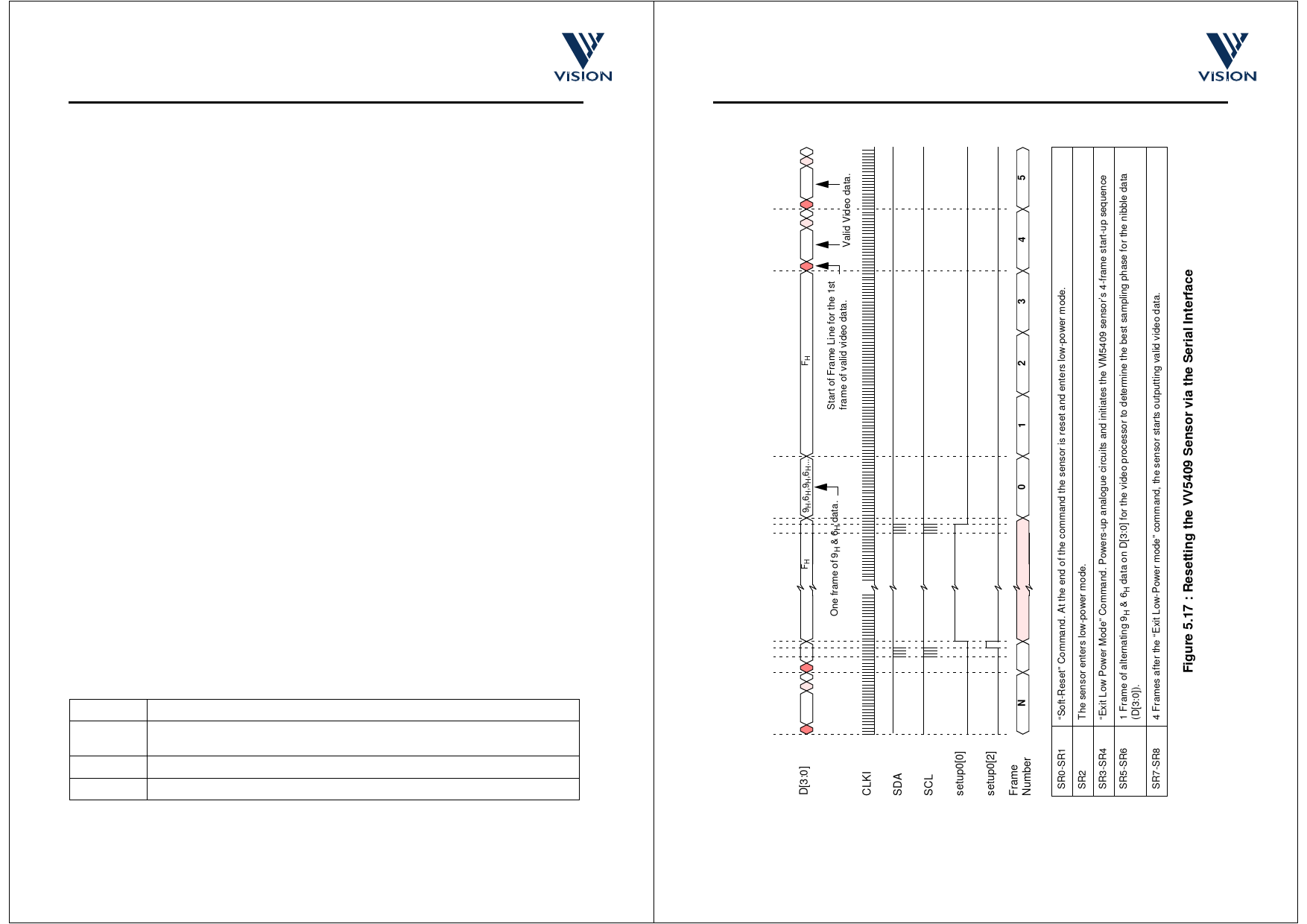
5.5 Resetting the Sensor Via the Serial Interface
Bit 2 of setup register 0 allows the VV5409 sensor to be reset to its power-on state via the 2-wire serial
interface. Setting this “Soft Reset” bit causes all of the serial interface registers including the “Soft Reset” bit
to be reset to their default values. This “Soft Reset” leaves the sensor in low-power mode and thus an “Exit
Low-Power Mode” command (Table 6.7, Section 6.6.2) must be issued via the serial interface before the
sensor will start to generate video data (Figure 5.17).
5.6 Power-up, Low-power and Sleep modes
To clarify the state of the interface on power-up and in the case of a ‘hot’ connection of the interface cable
the power-up state of the bus is defined below.
PU0
System Power Up or Sensor Hot Plugged
PU1
Sensor Internal-on Reset Triggers, the sensor enters low power mode and D[3:0] is set
to FH.
PU2
Video Processor released from reset.
PU3
Video Processor enables the sensor clock, CLKI.
Table 5.5 : System Power-Up or Hot-plugging Device Behaviour
Commercial In Confidence
cd38041a.fm
08/10/98
33
VV5409 CMOS Monochrome Sensor Datasheet (Restricted) Rev 1.0
SR8
SR7
SR6
SR5
SR4
SR3
SR2
SR1
SR0
Commercial In Confidence
cd38041a.fm
08/10/98
34
Share Link: 