CS5112 View Datasheet(PDF) - Cherry semiconductor
Part Name
Description
View to exact match
CS5112
Cherry semiconductor

CS5112 Datasheet PDF : 10 Pages
| |||
Application Notes: continued
Step 4
Determine the maximum on time at the minimum oscilla-
tor frequency and VIN. For discontinuous operation, all of
the stored energy in the inductor is transferred to the load
prior to the next cycle. Since the current through the
inductor cannot change instantaneously and the induc-
tance is constant, a volt-second balance exists between the
on time and off time. The voltage across the inductor dur-
ing the on cycle is VIN and the voltage across the inductor
during the off cycle is VOUT - VIN. Therefore:
VINton = (VOUT -VIN)toff
(4a)
where the maximum on time is:
[ ] [ ] ton(max) Å
1 - VIN(min)
VOUT(max)
1
.
fSW(min)
(4b)
overall loop gain is 0dB at the crossover frequency, fCO. In
addition, the gain slope should be -20dB/decade at the
crossover frequency.
The low frequency gain of the modulator (i.e. error ampli-
fier output to output voltage) is:
ÆVOUT
ÆVEA
à = Ipk(max)
VEA(max)
RLoad L f
2
,
(8a)
where
Ipk(max) =
VEA(max)/GCSA
RS
=
(2.4V)/(7)
150m½
=2.3A.
The VOUT/VEA transfer function has a pole at:
fp = 1/(¹RLoadCOUT) ,
(8b)
and a zero due to the output capacitorÕs ESR at:
Step 5
Calculate the maximum inductance allowed for discontin-
uous operation:
L(max) =
fSW(min) VIN2(min) ton2(max)
2 POUT/h
(5)
where h = efficiency.
fz = 1/(2¹ESR COUT).
(8c)
Since the error amplifier reference voltage is 1.25V, the
output voltage must be divided down or attenuated
before being applied to the input of the error amplifier.
The feedback resistor divider attenuation is:
1.25V .
VOUT
Usually h = 0.75 is a good starting point. The ICÕs power
dissipation should be calculated after the peak current has
been determined in Step 6. If the efficiency is less than
originally assumed, decrease the efficiency and recalculate
the maximum inductance and peak current.
Step 6
Determine the peak inductor current at the minimum
inductance, minimum VIN and maximum on time to make
sure the inductor current doesnÕt exceed 1.4A.
The error amplifier in the CS5112 is an operational transcon-
ductance amplifier (OTA), with a gain given by:
GOTA = gmZOUT
(8d)
where:
gm = ÆIOUT .
(8e)
ÆVIN
For the CS5112, gm = 2700µA/V typical.
Ipk =
VIN(min) ton(max)
L(min)
One possible error amplifier compensation scheme is
(6)
shown in Figure 9. This gives the error amplifier a gain
plot as shown in Figure 10.
Step 7
Determine the minimum output capacitance and maxi-
mum ESR based on the allowable output voltage ripple.
COUT(min) =
Ipk
8fÆVripple
(7a)
ESR(min) =
ÆVripple
Ipk
(7b)
In practice, it is normally necessary to use a larger capaci-
tance value to obtain a low ESR. By placing capacitors in
parallel, the equivalent ESR can be reduced.
For the error amplifier gain shown in Figure 10, a low fre-
quency pole is generated by the error amplifier output
impedance and C1. This is shown by the line AB with a -
20dB/decade slope in Figure 12. The slope changes to zero
at point B due to the zero at:
fz = 1/(2¹R4C1).
(8f)
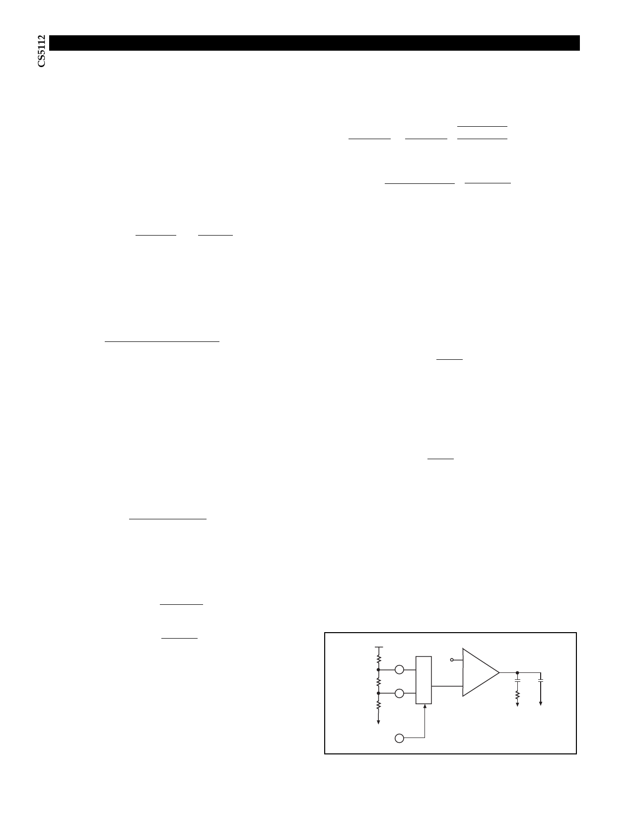
VOUT
R1
VFB1
M
R2
VFB2
U
X
R3
1.25V
+
Ð
C1
C2
Error
R4
Amplifier
Step 8
Compensate the feedback loop to guarantee stability
under all operating conditions. To do this, we calculate the
modulator gain and the feedback resistor network attenu-
ation and set the gain of the error amplifier so that the
SELECT
Figure 9. RC network used to compensate the error amplifier (OTA).
8
Share Link: