DEHR33D102KA3B View Datasheet(PDF) - Unspecified
Part Name
Description
View to exact match
DEHR33D102KA3B Datasheet PDF : 74 Pages
| |||
!Note • Please read rating and !CAUTION (for storage, operating, rating, soldering, mounting and handling) in this catalog to prevent smoking and/or burning, etc.
• This catalog has only typical specifications. Therefore, please approve our product specifications or transact the approval sheet for product specifications before ordering.
C85E.pdf
Sep.14,2018
Type EA Specifications and Test Methods
1
Operating Temperature Range: -40 to +125°C
No.
Item
Specifications
Test Method
1 Appearance
2 Dimensions
3 Dielectric Strength
4 Insulation Resistance (I.R.)
5 Capacitance
6 Dissipation Factor (D.F.)
7
Capacitance Temperature
Characteristics
No defects or abnormalities
Within specified dimension
No defects or abnormalities
6000MΩ or more
Within the specified tolerance
0.025 max.
Temp. Coefficient
SL: +350 to -1000 ppm/°C
(Temp. Range: +20 to +85°C)
Cap. Change
B5'2&',{z
B5'2&',|zGQ
(Temp. Range: -25 to +85°C)
Visual Inspection.
Using calipers and micrometers.
The capacitor shall not be damage when AC4000V(r.m.s.) is
applied between the terminations for 60s.
The insulation resistance shall be measured with DC500±50V
within 60±5s of charging.
The voltage should be applied to the capacitor through a
resistor of 1MΩ.
Capacitance/D.F. shall be measured at 20°C with the
frequency of 1±0.2kHz and a voltage of AC1±0.2V(r.m.s.).
The capacitance measurement shall be made at each step in
table.
F0#20# 2+#,2$-0A !& 0@
Perform the heat treatment at 150+0/-10°C for 60±5min
and then let sit for 24±2h at room condition*.
Step
1
2
3
4
5
Temp. (°C) 20±2 -25±2 20±2 85±2 20±2
8
Vibration
Resistance
Appearance
Capacitance
D.F.
9 Solderability of Termination
Soldering
10 Effect
(Reflow)
Appearance
Capacitance
I.R.
Dielectric
Strength
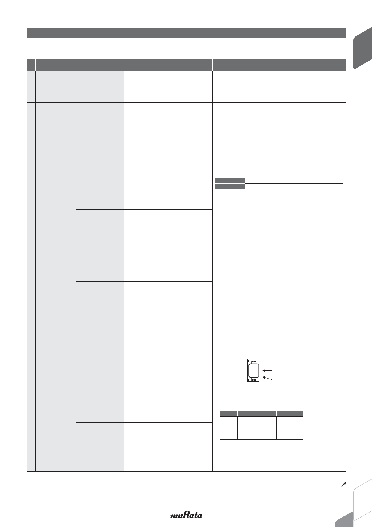
11
Adhesive strength of
Termination
No marked defect
Within the specified tolerance
Pass the item No.6
75% of the terminations are to be
soldered.
No marked defects
Within ±10%
1000MΩ or more
Pass the item No.3
No removal of the terminations or other
defects should occur.
Solder the capacitor to the Test Jig a (glass epoxy board)
shown in "Complement of test method".
The capacitor shall be subjected to a simple harmonic motion
having a total amplitude of 1.5mm, the frequency being varied
uniformly between the approximate limits of 10 and 55Hz.
The frequency range, from 10 to 55Hz and return to 10Hz, shall
be traversed in approximately 1min.
This motion shall be applied for a period of 2h in each of 3
mutually perpendicular directions (total of 6h).
Immerse the capacitor in the solution of ethanol (JIS K 8101)
and rosin (JIS K 5902) (25% rosin in weight proportion).
Immerse in solder solution for 2±0.5s.
Temp. of solder: 245±5°C
Preheat the capacitor at 150 to 180°C for 90±30s.
Reflow temp.: 230°C min. (max. temp.: 260°C)
Reflow time: 30±10s.
Reflow number of times: 4 times
Let sit at room condition* for 24±2h, then measure.
F&#,#620#$*-5.-0!#111&-3*" #"-,# $2#02#+.#0 230#
of the sample has dropped to room temperature.
F0#20# 2+#,2$-0A !& 0@
Capacitor should be stored at 150+0/-10°C for 1h, and apply
the AC4000V(r.m.s.) 60s then placed at room condition* for
24±2h before initial measurements.
Solder the capacitor to the Test Jig a (glass epoxy board)
shown in "Complement of test method".
Then apply 10N force in the direction of the arrow.
10N, 10±1s
* 11 .-67- 0"
12
Temperature
Cycle
Appearance
Capacitance
Change
D.F.
I.R.
No marked defect
Within ±15%
SL: 0.025 max.
A B0.05 max.
3000MΩ or more
Dielectric Strength Pass the item No.3
Fix the capacitor to the supporting Test Jig A (glass epoxy
board) shown in "Complement of test method".
Perform the 5 cycles according to the 4 heat treatments listed
the following table.
Step
1
2
3
4
Temp. (°C)
-40±3
Room Temp.
125±3
Room Temp.
Time (min.)
30±3
2 to 3
30±3
2 to 3
Let sit for 24±2h, at room condition*, then measure.
F0#20# 2+#,2$-0A !& 0@
Capacitor should be stored at 150+0/-10°C for 1h, and apply
the AC4000V(r.m.s.) 60s then placed at room condition* for
24±2h berore initial measurements.
* "Room condition" Temperature: 15 to 35°C, Relative humidity: 45 to 75%, Atmosphere pressure: 86 to 106kPa
Continued on the following page.
7
Share Link: 