VP513 View Datasheet(PDF) - SANYO -> Panasonic
Part Name
Description
View to exact match
VP513 Datasheet PDF : 8 Pages
| |||
VP513
Thermal Design for the VP513
Since the VP513 includes three channels, we first consider a single channel. The chip temperature of each transistor
under actual operating conditions is determined using the following formula.
Tj = (Tri) = θj-c (Tri) × Pc (Tri) + ∆Tc + Ta [°C] .................................. (1)
θj-c (Tri): Thermal resistance of an individual transistor
Pc (Tri): Collector loss for an individual transistor
∆Tc: Case temperature rise
Ta:
Ambient temperature
The θj-c(Tri) for each chip is:
θj-c (Tr1) = 45°C/W/θj-c (Tr2) to (Tr4) = 35°C/W................................ (2)
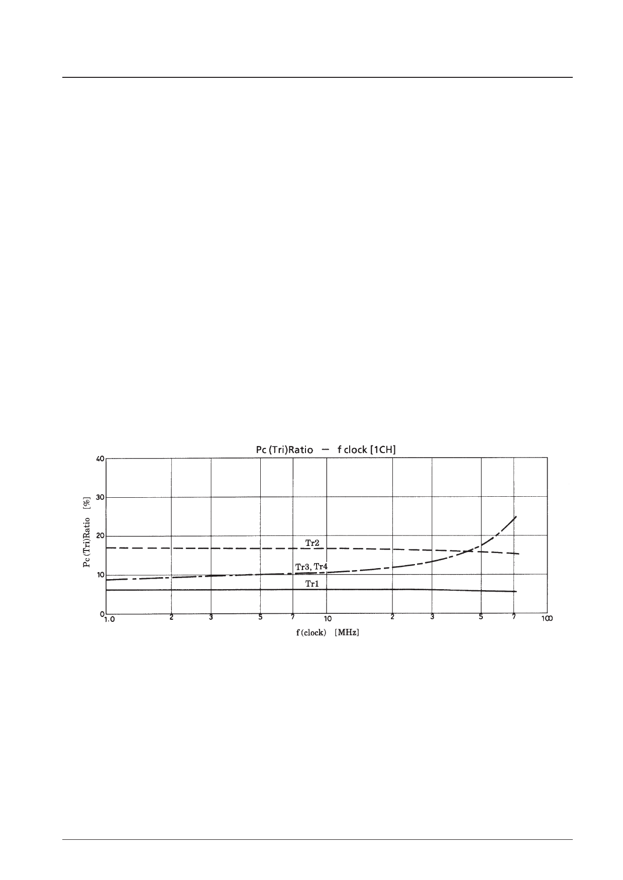
Although the loss for each transistor in a Video Pack varies with frequency and is not uniform, if we assume that the
maximum operating frequency, f = 70 MHz (clock), then the chips with the largest loss will be transistors 3 and 4 (Tr3
and Tr4) and that loss will be about 1/4 of the total loss.Thus from the Pd for a single channel we have:
Pc (Tr3) 70 MHz = Pd (1CH) 70 MHz × 1/4.......................................... (3)
Here, we must select a heat sink with a capacity θh such that the Tj of these transistors does not exceed 150°C. Equation
(4) below gives the relationship between θh and ∆Tc.
∆Tc = Pd (TOTAL) × θh ........................................................................ (4)
The required θh is calculated using this equation and equation (1).
No. 5331-5/8
Share Link: 