M27V102 View Datasheet(PDF) - STMicroelectronics
Part Name
Description
View to exact match
M27V102 Datasheet PDF : 15 Pages
| |||
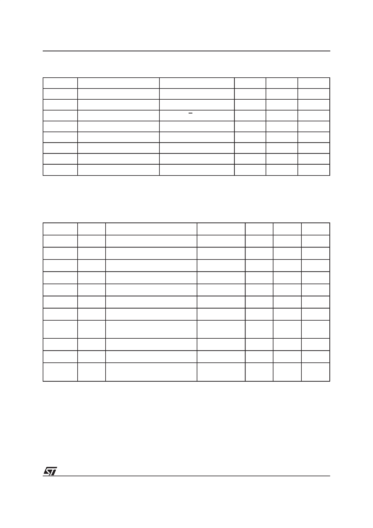
M27V102
Table 9. Programming Mode DC Characteristics (1)
(TA = 25 °C; VCC = 6.25V ± 0.25V; VPP = 12.75V ± 0.25V)
Symbol
Parameter
Test Condition
Min
Max
ILI
Input Leakage Current
0 ≤ VIN ≤ VIH
±10
ICC
Supply Current
50
IPP
Program Current
VIL
Input Low Voltage
VIH
Input High Voltage
E = VIL
–0.3
2
50
0.8
VCC + 0.5
VOL
Output Low Voltage
IOL = 2.1mA
VOH
Output High Voltage TTL
IOH = –400µA
2.4
VID
A9 Voltage
11.5
Note: 1. VCC must be applied simultaneously with or before VPP and removed simultaneously with or after VPP.
0.4
12.5
Unit
µA
mA
mA
V
V
V
V
V
Table 10. Programming Mode AC Characteristics (1)
(TA = 25 °C; VCC = 6.25V ± 0.25V; VPP = 12.75V ± 0.25V)
Symbol
Alt
Parameter
Test Condition
Min
tAVPL
tAS
Address Valid to Program Low
2
tQVPL
tDS
Input Valid to Program Low
2
tVPHPL
tVPS VPP High to Program Low
2
tVCHPL
tVCS VCC High to Program Low
2
tELPL
tCES Chip Enable Low to Program Low
2
tPLPH
tPW
Program Pulse Width
95
tPHQX
tDH
Program High to Input Transition
2
tQXGL
tOES
Input Transition to Output Enable
Low
2
tGLQV
tOE
Output Enable Low to Output Valid
tGHQZ (2)
tDFP Output Enable High to Output Hi-Z
0
tGHAX
tAH
Output Enable High to Address
Transition
0
Notes: 1. VCC must be applied simultaneously with or before VPP and removed simultaneously with or after VPP.
2. Sampled only, not 100% tested.
Max
105
100
130
Unit
µs
µs
µs
µs
µs
µs
µs
µs
ns
ns
ns
7/15
Share Link: 