IDT72510L25J View Datasheet(PDF) - Integrated Device Technology
Part Name
Description
View to exact match
IDT72510L25J
Integrated Device Technology

IDT72510L25J Datasheet PDF : 32 Pages
| |||
IDT72510, IDT72520
BUS MATCHING BIDIRECTIONAL FIFO
36-BIT PROCESSOR to 18-BIT PERIPHERAL CONFIGURATION
COMMERCIAL TEMPERATURE RANGE
Processor
Address
Control
Data
36
RAM
IDT
BiFIFO
(Stand-Alone)
Cntl A Cntl B
ACK
REQ
CLK
Data A Data B
IDT
BiFIFO
(Stand-Alone)
Cntl A Cntl B
ACK
REQ
CLK
Data A Data B
18
9
DMA or System
Clock
Peripheral
Controller
Cntl
ACK
REQ
Data
I/O
Data
18
2669 drw 05
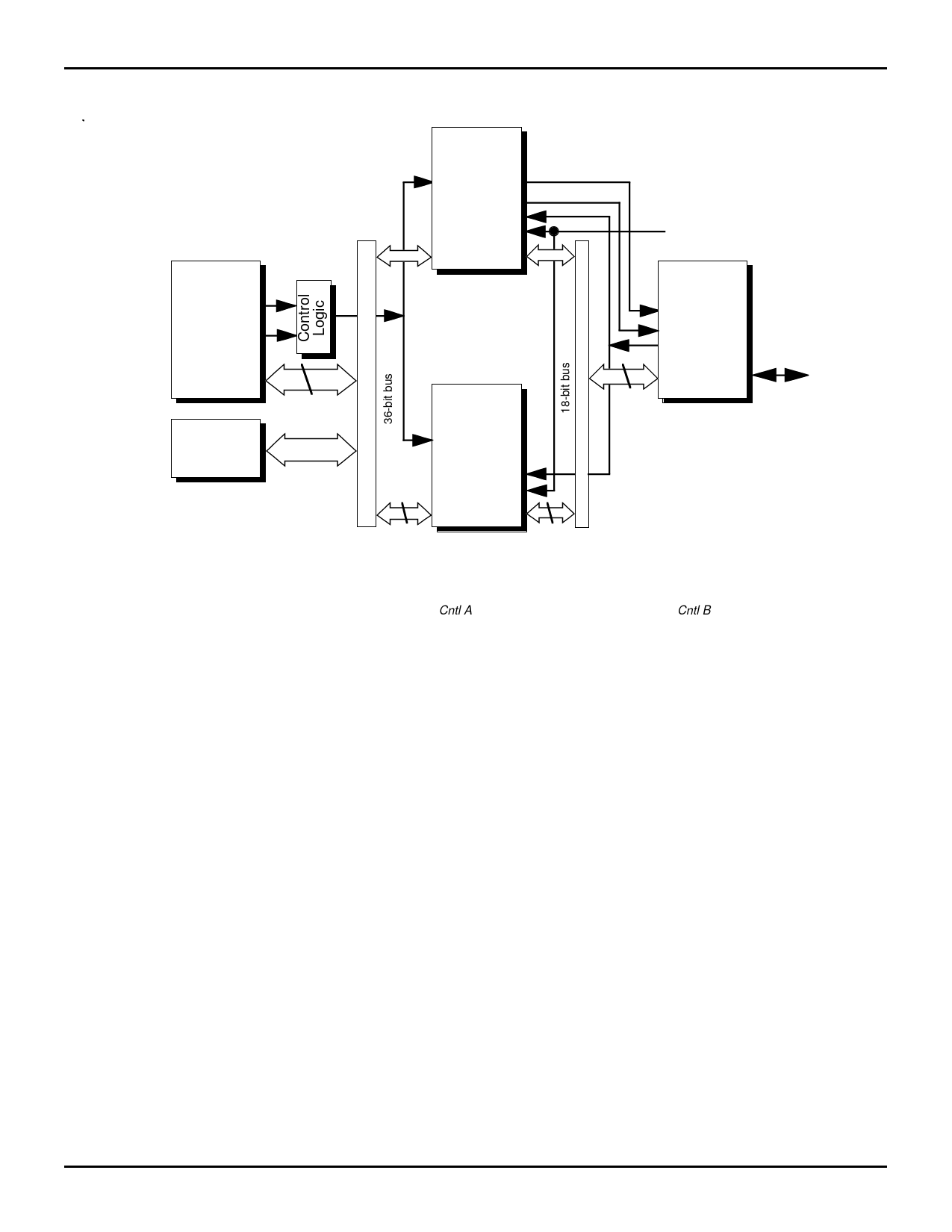
Figure 2. 36- to 18-Bit Peripheral Interface Configuration
NOTE:
DS 1. Upper BiFIFO only is used in 18- to 9-bit configuration. Note that Cntl A refers to CSA, A1, A0, R/WA and DSA; Cntl B refers to R/WB and B or RB
and WB.
talk to a 9-bit processor or a 9-bit peripheral. Both BiFIFOs
are programmed simultaneously through Port A by placing
one command word on the most significant 16 data bits and
one command word on the least significant 16 data bits
(parity bits should be ignored).
One BiFIFO must be programmed as the master device
and the other BiFIFO is the slave device. Bits 11 and 12 of
Configuration Register 5 are set to 10 for the slave device
and 11 for the master device. The first two 9-bit words on
Port B are read from or written to the slave device and the
next two 9-bit words go to the master device.
When both BiFIFOs are in peripheral interface mode, the
Port B interface pins of the master device are outputs and
this BiFIFO controls the bus. The Port B interface pins of the
slave device are inputs driven by the master BiFIFO. Two
BiFIFOs are connected in Figure 4 to create a 36- to 9-bit
peripheral interface.
The two BiFIFOs shown in Figure 3 are configured to
connect a 36-bit processor to a 9-bit processor.
36- to 18-bit Configurations
In a 36- to 18-bit configuration, two BiFIFOs operate in
parallel. Both BiFIFOs are programmed simultaneously, 16
data bits to each device with the 4 parity bits ignored.
Both BiFIFOs must be programmed into stand-alone mode
for a 36-bit processor to communicate with an 18-bit proces-
sor or an 18-bit peripheral. This means that bits 11 and 12 of
Configuration Register 5 must be set to 00.
This configuration can be extended to wider bus widths
(54- to 27-bits, 72- to 36-bits, …) by adding more BiFIFOs to
the configuration. Figures 1 and 2 show multiple BiFIFOs
configured for processor and peripheral interface modes
respectively.
Processor Interface Mode
When a microprocessor or microcontroller is connected to
Port B, all BiFIFOs in the configuration must be programmed
to processor interface mode. In this mode, all Port B interface
controls are inputs. Both REQ and CLK pins should be pulled
LOW to ensure that the set-up and hold time requirements for
these pins are met during reset. Figures 1 and 3 show
BiFIFOs in processor interface mode.
Peripheral Interface Mode
If Port B is connected to a peripheral controller, all BiFIFOs
in the configuration must be programmed in the peripheral
interface mode. To assure fixed high states for RB and WB
before they are programmed into an output, both pins should
be pulled-up to VCC with 10K resistors.
If the BiFIFOs are in stand-alone configuration mode
(18- to 9-bit, 36- to 18-bit, …), then the Port B interface pins are
all outputs. Of course, only one set of Port B interface pins
should be used to control a single peripheral device, while the
other interface pins are all ignored. Figure 2 shows stand-
5.31
7
Share Link: