ISL97634 查看數據表(PDF) - Renesas Electronics
零件编号
产品描述 (功能)
生产厂家
ISL97634 Datasheet PDF : 12 Pages
| |||
ISL97634
PART NO.
ISL97634IRT14Z
ISL97634IRT18Z
ISL97634IRT26Z
TABLE 1.
OVP
14V
18V
26V
MAX ILED
70mA
50mA
30mA
Shutdown
When PWM/EN is taken low the ISL97634 enters into the
power-down mode where the supply current is reduced to less
than 1µA. The device resumes normal when the PWM/EN goes
high.
Components Selection
The input capacitance is typically 0.22µF. The output capacitor
should be in the range of 0.22µF to 1µF. X5R or X7R type of
ceramic capacitors of the appropriate voltage rating are
recommended.
When choosing an inductor, make sure the average and peak
current ratings are adequate by using Equations 3, 4 and 5 (80%
efficiency assumed):
ILAVG = -I-L----E0---.-D-8-------V-V---O-I--N--U----T-
ILPK = ILAVG + 12-- IL
(EQ. 3)
(EQ. 4)
IL = V-----IL--N------V----OV----U-O----TU----T---f--–O----V-S----CI--N----
Where:
(EQ. 5)
• IL is the peak-to-peak inductor current ripple in Amps
• L is the inductance in H
• fOSC is the switching frequency, typically 1.45MHz
The ISL97634 supports a wide range of inductance values (10µH
to ~82µH). For lower inductor values or lighter loads, the boost
inductor current may become discontinuous. For high boost
inductor values, the boost inductor current will be in continuous
mode.
In addition to the inductor value and switching frequency, the
input voltage, number of LEDs and the LED current also affects
whether the converter operates in continuous conduction or
discontinuous conduction mode. Both operating modes are
allowed and normal. The discontinuous conduction mode yields
lower efficiency due to higher peak current.
Compensation
The product of the output capacitor and the load create a pole
while the inductor creates a right half plane zero. Both of these
attributes degrade the phase margin but the ISL97634 has
internal compensation network that ensures the device operates
reliably under the specified conditions. The internal
compensation and the highly integrated functions of the
ISL97634 make it a design friendly device to be used in high
volume, high reliability applications.
Applications
Analog Dimming
Analog dimming is usually not recommended because of the
brightness non-linearity at low levels dimming. However, some
systems are EMI or noise sensitive that analog dimming may be
more suitable than PWM dimming under those situations. The
ISL97632 is part of the same family as the ISL97634 and has
been designed with a serial interface to give access to 32
separate dimming levels. Alternatively analog dimming can be
achieved by applying a variable DC voltage (VDim) at the FB pin
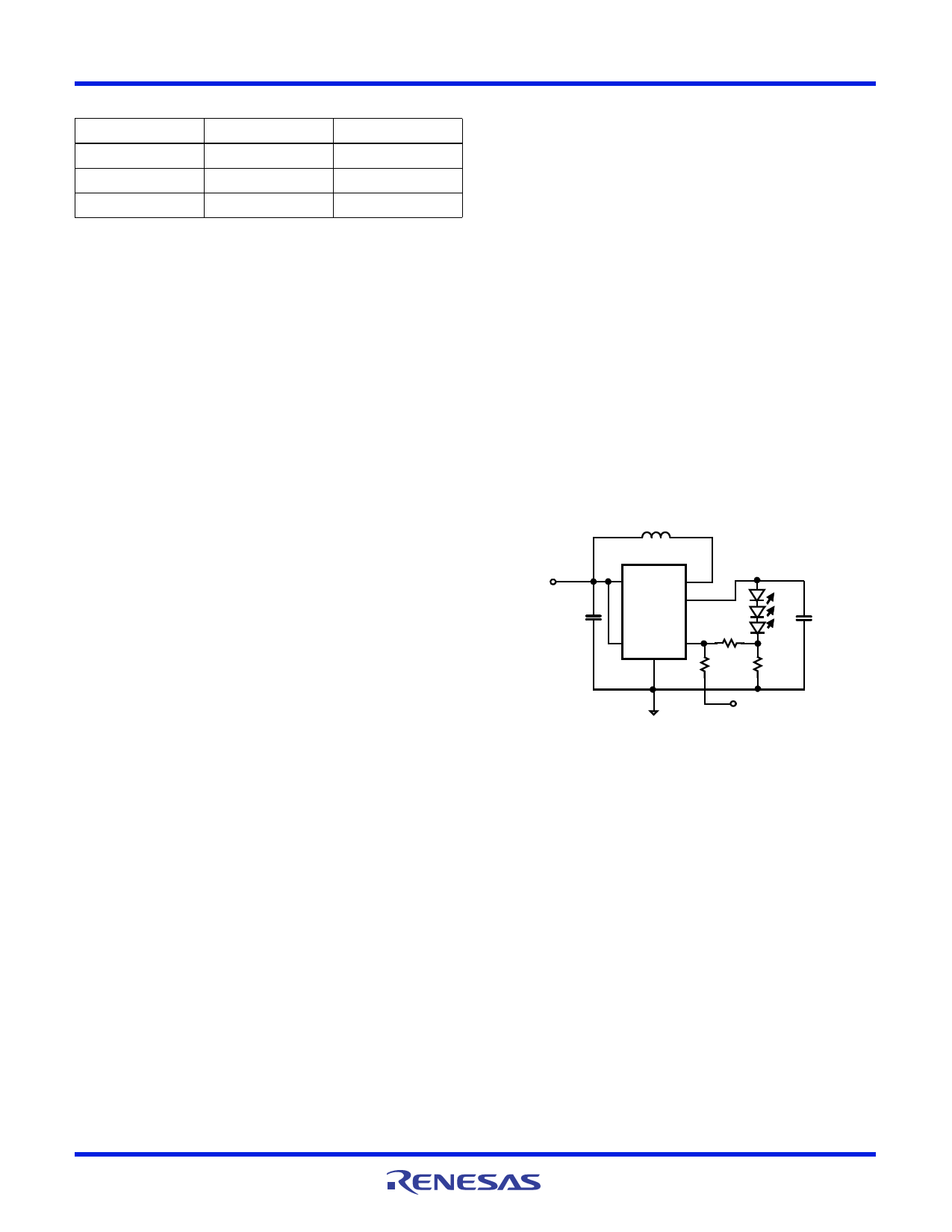
(see Figure 15) to adjust the LED current. As the DC dimming
signal voltage increases above VFB, the voltage drop on R1 and
R2 increases and the voltage drop on RSET decreases. Thus, the
LED current decreases as shown in Equation 6:
ILED = V-----F---B-----------R----1-R----+2-----R---R-2---S----–E----T-V----D----i--m--------R-----1-
(EQ. 6)
If VDIM is taken below FB, the inverse will happen and the
brightness will increase.
The DC dimming signal voltage can be a variable DC voltage from
a POT, a DCP (Digitally Controlled Potentiometer), or a DC voltage
generated by filtering a high frequency PWM control signal.
L1
VIN
3.3V
C1
1µF
22µH
VIN
LX
VOUT
ISL97634
PWM
GND
FB
R2
LEDs
C2
R1
0.22µF
3.3k
RSET
4.75
VDim
FIGURE 15. ANALOG DIMMING CONTROL APPLICATION CIRCUIT
As brightness is directly proportional to LED currents, VDim may
be calculated for any desired “relative brightness” (F) using
Equation 7:
VDim
=
RR-----21-
VFB
1
+
RR-----12-
–
F
(EQ. 7)
Where F = ILED (dimmed)/ILED (undimmed).
These equations are valid for values of R1 and R2 such that both
R1>>RSET and R2>>RSET.
The analog dimming circuit can be tailored to a desired relative
brightness for different VDim ranges using Equation 8.
R2 = -----V-----D--V--i-m-F----B_---m----a---x--1---–--–--V--F--F--m--B---i-n--------R----1----
(EQ. 8)
Where VDim_max is the maximum VDim voltage and Fmin is the
minimum relative brightness (i.e., the brightness with VDim_max
applied).
i.e., VDim_max = 5V, Fmin = 10% (i.e., 0.1), R2 = 189k
i.e., VDim_max = 1V, Fmin = 10% (i.e., 0.1), R2 = 35k
FN6264 Rev 4.00
August 27, 2013
Page 8 of 12
Share Link: 