MC10E404(2016) 查看數據表(PDF) - ON Semiconductor
零件编号
产品描述 (功能)
生产厂家
MC10E404 Datasheet PDF : 7 Pages
| |||
MC10E404, MC100E404
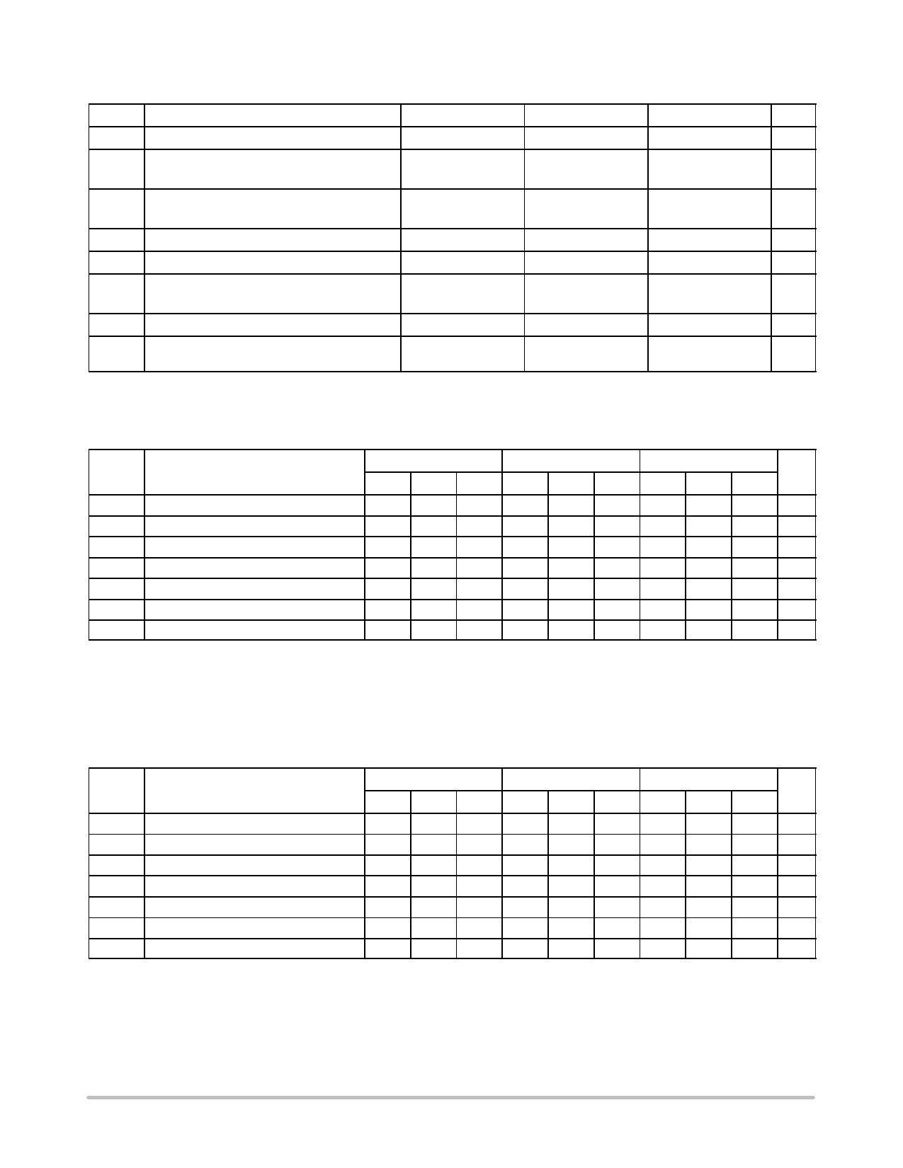
Table 3. MAXIMUM RATINGS
Symbol
Parameter
Condition 1
Condition 2
Rating
Unit
VCC PECL Mode Power Supply
VI
PECL Mode Input Voltage
NECL Mode Input Voltage
Iout Output Current
VEE = 0 V
VEE = 0 V
VCC = 0 V
Continuous
Surge
VI ≤ VCC
VI ≥ VEE
8
V
6
V
−6
50
mA
100
TA
Operating Temperature Range
Tstg Storage Temperature Range
qJA Thermal Resistance (Junction-to-Ambient)
0 lfpm
500 lfpm
PLCC−28
0 to +85
−65 to +150
63.5
43.5
°C
°C
°C/W
qJC Thermal Resistance (Junction-to-Case)
Tsol Wave Solder (Pb-Free)
Standard Board
PLCC−28
22 to 26
265
°C/W
°C
Stresses exceeding those listed in the Maximum Ratings table may damage the device. If any of these limits are exceeded, device functionality
should not be assumed, damage may occur and reliability may be affected.
Table 4. 10E SERIES PECL DC CHARACTERISTICS (VCCx = 5.0 V, VEE = 0.0 V (Note 1))
0°C
25°C
85°C
Symbol
IEE
VOH
VOL
VIH
VIL
IIH
IIL
Characteristic
Power Supply Current
Output HIGH Voltage (Note 2)
Output LOW Voltage (Note 2)
Input HIGH Voltage
Input LOW Voltage
Input HIGH Current
Input LOW Current
Min
3980
3050
3830
3050
0.5
Typ
106
4070
3210
3995
3285
0.3
Max
127
4160
3370
4160
3520
150
Min
4020
3050
3870
3050
0.5
Typ
106
4105
3210
4030
3285
0.25
Max
127
4190
3370
4190
3520
150
Min
4090
3050
3940
3050
0.3
Typ
106
4185
3227
4110
3302
0.2
Max Unit
127 mA
4280 mV
3405 mV
4280 mV
3555 mV
150 mA
mA
NOTE: Device will meet the specifications after thermal equilibrium has been established when mounted in a test socket or printed circuit
board with maintained transverse airflow greater than 500 lfpm. Electrical parameters are guaranteed only over the declared
operating temperature range. Functional operation of the device exceeding these conditions is not implied. Device specification limit
values are applied individually under normal operating conditions and not valid simultaneously.
1. Input and output parameters vary 1:1 with VCC. VEE can vary −0.46 V / +0.06 V.
2. Outputs are terminated through a 50 W resistor to VCC − 2.0 V.
Table 5. 10E SERIES NECL DC CHARACTERISTICS (VCCx = 0.0 V; VEE = −5.0 V (Note 1))
0°C
25°C
85°C
Symbol
Characteristic
Min Typ Max Min Typ Max Min Typ Max Unit
IEE Power Supply Current
106 127
106 127
106 127 mA
VOH Output HIGH Voltage (Note 2)
−1020 −930 −840 −980 −895 −810 −910 −815 −720 mV
VOL Output LOW Voltage (Note 2)
−1950 −1790 −1630 −1950 −1790 −1630 −1950 −1773 −1595 mV
VIH Input HIGH Voltage
−1170 −1005 −840 −1130 −970 −810 −1060 −890 −720 mV
VIL Input LOW Voltage
−1950 −1715 −1480 −1950 −1715 −1480 −1950 −1698 −1445 mV
IIH
Input HIGH Current
150
150
150 mA
IIL
Input LOW Current
0.5 0.3
0.5 0.065
0.3 0.2
mA
NOTE: Device will meet the specifications after thermal equilibrium has been established when mounted in a test socket or printed circuit
board with maintained transverse airflow greater than 500 lfpm. Electrical parameters are guaranteed only over the declared
operating temperature range. Functional operation of the device exceeding these conditions is not implied. Device specification limit
values are applied individually under normal operating conditions and not valid simultaneously.
1. Input and output parameters vary 1:1 with VCC. VEE can vary −0.46 V / +0.06 V.
2. Outputs are terminated through a 50ĂW resistor to VCC − 2.0 V.
www.onsemi.com
3
Share Link: 