M27W101-80B6TR 查看數據表(PDF) - STMicroelectronics
零件编号
产品描述 (功能)
生产厂家
M27W101-80B6TR Datasheet PDF : 23 Pages
| |||
Device description
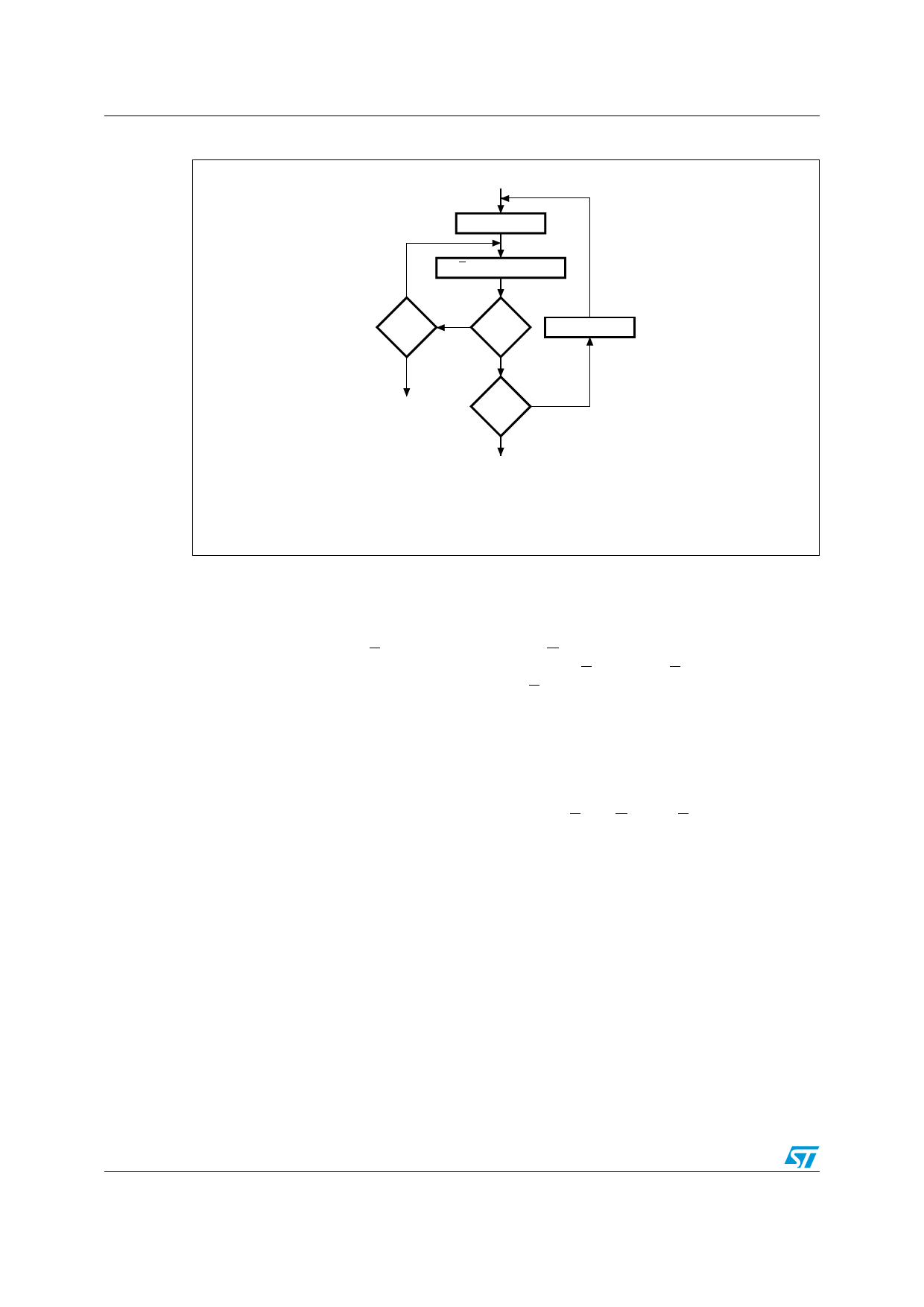
Figure 5. Programming Flowchart
VCC = 6.25V, VPP = 12.75V
n=0
NO
++n
= 25
YES
P = 100µs Pulse
NO
VERIFY
YES
++ Addr
FAIL
Last NO
Addr
YES
CHECK ALL BYTES
1st: VCC = 5V
2nd: VCC = 2.7V
AI00715D
M27W101
2.7
Program Inhibit
Programming of multiple M27W101s in parallel with different data is also easily
accomplished. Except for E, all like inputs including G of the parallel M27W101 may be
common. A TTL low level pulse applied to a M27W101's P input, with E low and VPP at
12.75V, will program that M27W101. A high level E input inhibits the other M27W101s from
being programmed.
2.8
Program Verify
A verify (read) should be performed on the programmed bits to determine that they were
correctly programmed. The verify is accomplished with E and G at VIL, P at VIH, VPP at
12.75V and VCC at 6.25V.
2.9
Electronic Signature
The Electronic Signature (ES) mode allows the reading out of a binary code from an
EPROM that will identify its manufacturer and type. This mode is intended for use by
programming equipment to automatically match the device to be programmed with its
corresponding programming algorithm. The ES mode is functional in the 25°C ± 5°C
ambient temperature range that is required when programming the M27W101. To activate
the ES mode, the programming equipment must force 11.5V to 12.5V on address line A9 of
the M27W101, with VPP = VCC = 5V. Two identifier bytes may then be sequenced from the
device outputs by toggling address line A0 from VIL to VIH. All other address lines must be
held at VIL during Electronic Signature mode.
10/23
Share Link: 