74AC153 查看數據表(PDF) - ON Semiconductor
零件编号
产品描述 (功能)
生产厂家
74AC153 Datasheet PDF : 9 Pages
| |||
MC74AC153, MC74ACT153
Ea I0a I1a I2a I3a I0b I1b I2b I3b Eb
S0
S1
Za
Zb
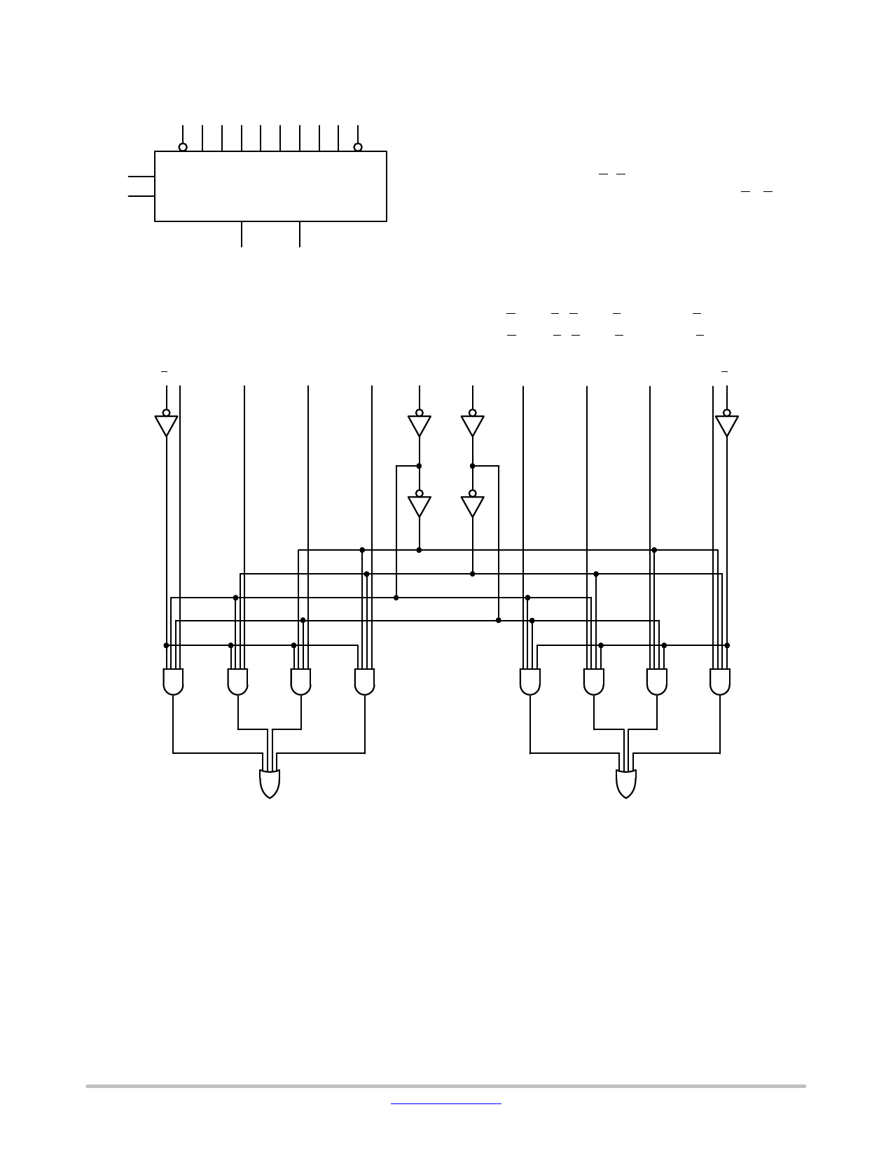
Figure 2. Logic Symbol
Ea I0a
I1a
I2a
I3a
S1
FUNCTIONAL DESCRIPTION
The MC74AC153/74ACT153 is a dual 4−input
multiplexer. It can select two bits of data from up to four
sources under the control of the common Select inputs (S0,
S1). The two 4−input multiplexer circuits have individual
active−LOW Enables (Ea,Eb) which can be used to strobe
the outputs independently. When the Enables (Ea, Eb) are
HIGH, the corresponding outputs (Za, Zb) are forced LOW.
The MC74AC153/74ACT153 is the logic implementation
of a 2−pole, 4−position switch, where the position of the
switch is determined by the logic levels supplied to the two
Select inputs. The logic equations for the outputs are shown
below.
Za = Ea•(I0a•S1•S0+I1a•S1•S0+I2a•S1•S0+I3a•S1•S0)
Zb = Eb•(I0b•S1•S0+I1b•S1•S0+I2b•S1•S0+I3b•S1•S0)
S0
I0b
I1b
I2b
I3b Eb
Za
Zb
NOTE:
This diagram is provided only for the understanding of logic
operations and should not be used to estimate propagation
delays.
Figure 3. Logic Diagram
www.onsemi.com
2
Share Link: 