USB2507 查看數據表(PDF) - Microchip Technology
零件编号
产品描述 (功能)
生产厂家
USB2507 Datasheet PDF : 42 Pages
| |||
USB2507
TABLE 5-5: RESET_N TIMING FOR DEFAULT/STRAP OPTION MODE (CONTINUED)
Name
Description
MIN
TYP
MAX
Units
t5 USB Attach (See Note).
100
msec
t6 Host acknowledges attach and signals USB Reset. 100
msec
t7 USB Idle.
undefined
msec
t8 Completion time for requests (with or without data
stage).
5
msec
Note 1: When in Bus-Powered mode, the Hub and its associated circuitry must not consume more than 100mA from
the upstream USB power source during t1+t5.
2: All Power Supplies must have reached the operating levels mandated in Section 7.0, "DC Parameters", prior
to (or coincident with) the assertion of RESET_N.
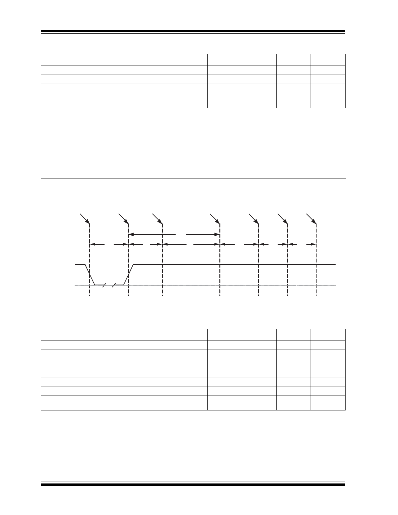
5.6.1.2 RESET_N for EEPROM Configuration
FIGURE 5-3:
RESET_N TIMING FOR EEPROM MODE
Hardware
reset
asserted
Read Strap
Options
Read EEPROM
+
Set Options
Attach
Start
USB
Upstream
USB Reset
recovery
Idle
completion
request
response
RESET_N
t4
t1
t2
t3
t5
t6
t7
VSS
TABLE 5-6: RESET_N TIMING FOR EEPROM MODE
Name
Description
MIN
TYP
MAX
Units
t1 RESET_N Asserted.
1
sec
t2 Hub Recovery/Stabilization.
500
sec
t3 EEPROM Read / Hub Config.
2.0
99.5
msec
t4 USB Attach (See Note).
100
msec
t5 Host acknowledges attach and signals USB Reset. 100
msec
t6 USB Idle.
undefined
msec
t7 Completion time for requests (with or without data
stage).
5
msec
Note 1: When in Bus-Powered mode, the Hub and its associated circuitry must not consume more than 100mA from
the upstream USB power source during t4+t5+t6+t7.
2: All Power Supplies must have reached the operating levels mandated in Section 7.0, "DC Parameters", prior
to (or coincident with) the assertion of RESET_N.
DS000002251A-page 28
2007 - 2016 Microchip Technology Inc.
Share Link: 