BC549 查看數據表(PDF) - Philips Electronics
零件编号
产品描述 (功能)
生产厂家
BC549 Datasheet PDF : 8 Pages
| |||
Philips Semiconductors
NPN general purpose transistors
Product specification
BC549; BC550
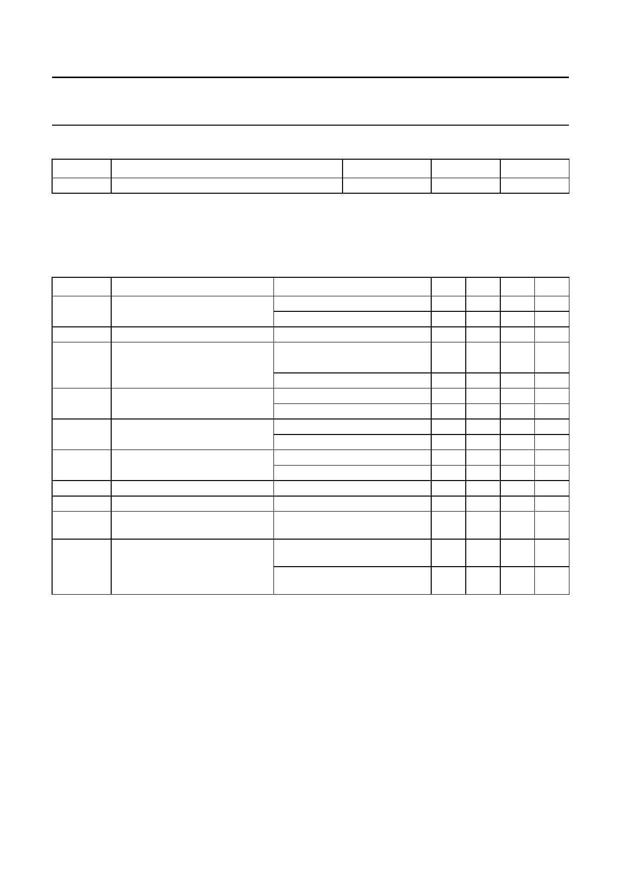
THERMAL CHARACTERISTICS
SYMBOL
PARAMETER
Rth j-a
thermal resistance from junction to ambient
Note
1. Transistor mounted on an FR4 printed-circuit board.
CONDITIONS
note 1
VALUE
250
UNIT
K/W
CHARACTERISTICS
Tj = 25 °C unless otherwise specified.
SYMBOL
ICBO
IEBO
hFE
VCEsat
VBEsat
VBE
Cc
Ce
fT
F
PARAMETER
collector cut-off current
emitter cut-off current
DC current gain
BC549C; BC550C
collector-emitter saturation voltage
base-emitter saturation voltage
base-emitter voltage
collector capacitance
emitter capacitance
transition frequency
noise figure
CONDITIONS
IE = 0; VCB = 30 V
IE = 0; VCB = 30 V; Tj = 150 °C
IC = 0; VEB = 5 V
IC = 10 µA; VCE = 5 V; see Fig.2
IC = 2 mA; VCE = 5 V; see Fig.2
IC = 10 mA; IB = 0.5 mA
IC = 100 mA; IB = 5 mA
IC = 10 mA; IB = 0.5 mA; note 1
IC = 100 mA; IB = 5 mA; note 1
IC = 2 mA; VCE = 5 V; note 2
IC = 10 mA; VCE = 5 V; note 2
IE = ie = 0; VCB = 10 V; f = 1 MHz
IC = ic = 0; VEB = 0.5 V; f = 1 MHz
IC = 10 mA; VCE = 5 V;
f = 100 MHz
IC = 200 µA; VCE = 5 V;
RS = 2 kΩ; f = 10 Hz to 15.7 kHz
IC = 200 µA; VCE = 5 V;
RS = 2 kΩ; f = 1 kHz; B = 200 Hz
MIN.
−
−
−
−
420
−
−
−
−
580
−
−
−
100
−
−
TYP.
−
−
−
270
520
90
200
700
900
660
−
1.5
11
−
−
−
MAX. UNIT
15 nA
5
µA
100 nA
−
800
250 mV
600 mV
−
mV
−
mV
700 mV
770 mV
−
pF
−
pF
−
MHz
4
dB
4
dB
Notes
1. VBEsat decreases by about 1.7 mV/K with increasing temperature.
2. VBE decreases by about 2 mV/K with increasing temperature.
1999 Apr 22
3
Share Link: 