74HC00-Q100 查看數據表(PDF) - NXP Semiconductors.
零件编号
产品描述 (功能)
生产厂家
74HC00-Q100 Datasheet PDF : 15 Pages
| |||
Nexperia
74HC00-Q100; 74HCT00-Q100
Quad 2-input NAND gate
9,
QHJDWLYH
SXOVH
*1'
9,
SRVLWLYH
SXOVH
*1'
90
WI
WU
90
9,
*
57
W:
W:
9&&
'87
90
WU
WI
90
92
&/
DDK
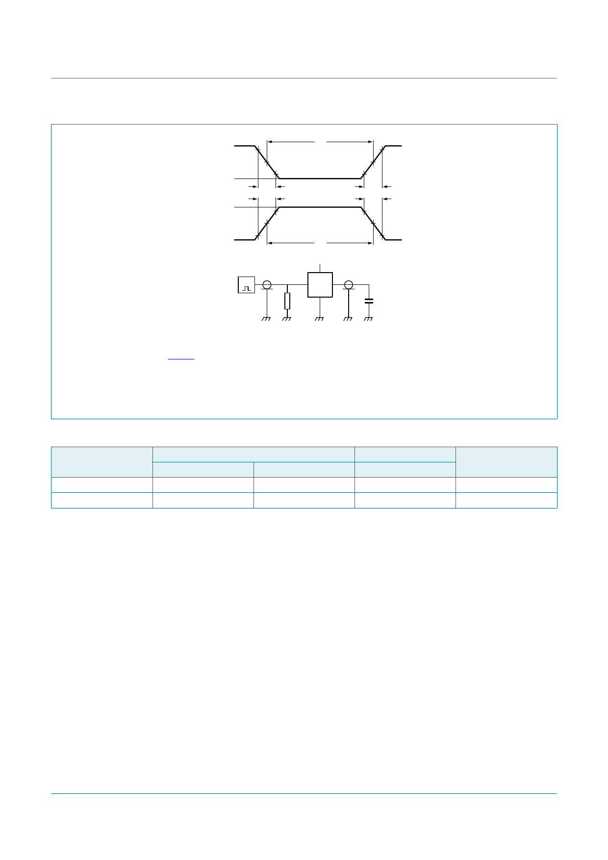
Fig 7.
Test data is given in Table 9.
Definitions test circuit:
RT = termination resistance should be equal to output impedance Zo of the pulse generator.
CL = load capacitance including jig and probe capacitance.
Test circuit for measuring switching times
Table 9. Test data
Type
74HC00-Q100
74HCT00-Q100
Input
VI
VCC
3.0 V
tr, tf
6.0 ns
6.0 ns
Load
CL
15 pF, 50 pF
15 pF, 50 pF
Test
tPLH, tPHL
tPLH, tPHL
74HC_HCT00_Q100
Product data sheet
All information provided in this document is subject to legal disclaimers.
Rev. 2 — 24 November 2015
© Nexperia B.V. 2017. All rights reserved
8 of 15
Share Link: 