VV6501 查看數據表(PDF) - STMicroelectronics
零件编号
产品描述 (功能)
生产厂家
VV6501 Datasheet PDF : 60 Pages
| |||
Functional Description
VV6501
3.3 Power management
3.3.1
Voltage regulators
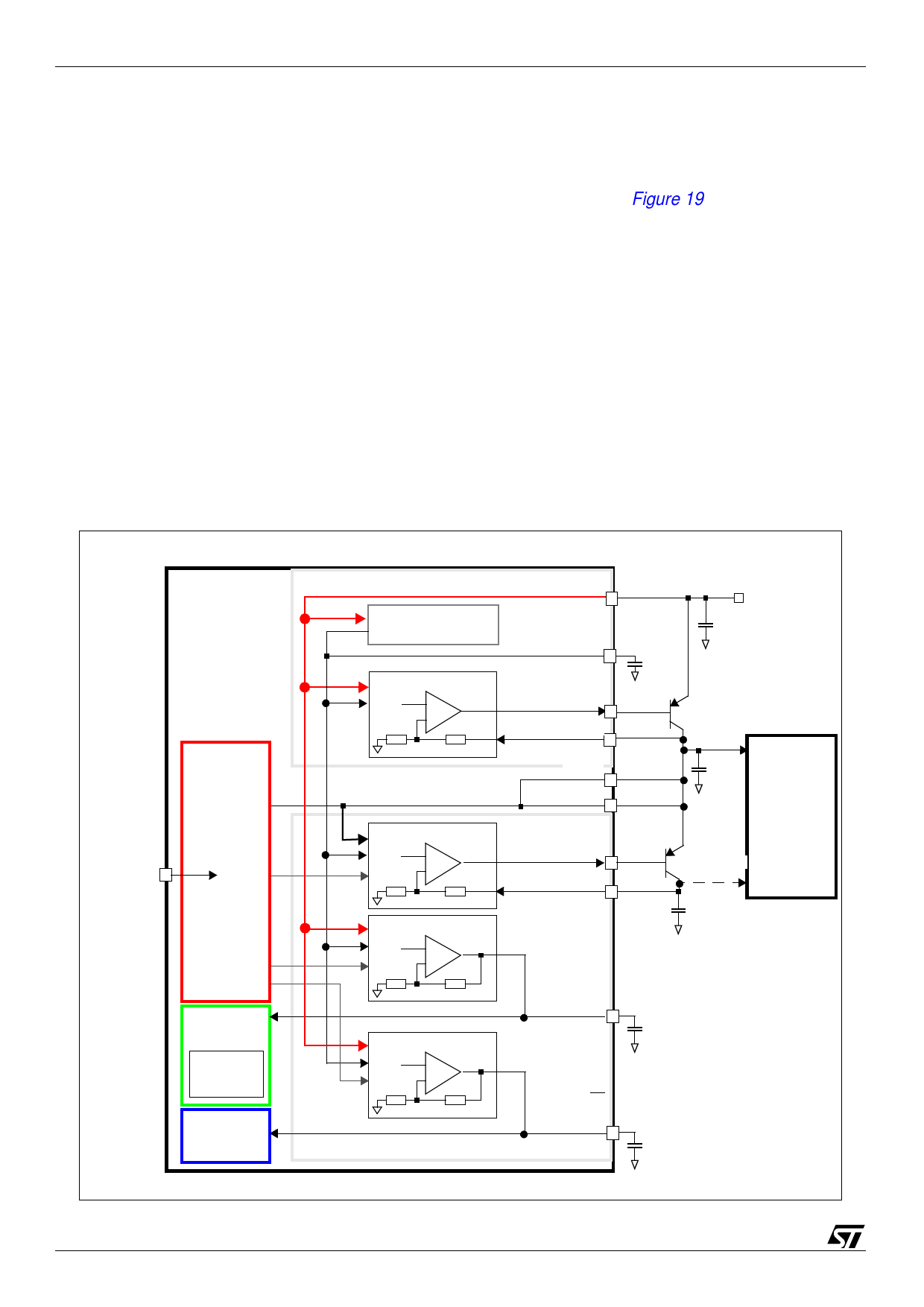
The power management block on the device avoids the requirement for any external system
regulators in a 5 V based camera product. The scheme is shown in Figure 19.
q Digital Regulator 1 - This 5 V to 3.3 V regulator uses an external bipolar transistor to supply
loads up to 200 mA. It is typically used to power the sensor digital logic and may also be used
to supply an external co-processor if required. This regulator is always on.
q Digital Regulator2 - This 3.3 V to 1.8 V regulator uses an external bipolar transistor to supply
loads up to 100 mA. This supply may be used for an external co-processor if required. This
regulator is controlled by the PDREG1V8 pin and must be switched off if not required.
q Audio Amp Regulator - This 5 V to 3.3 V regulator supplies the audio amplifier and the buffer
amplifier used to supply the reference to the microphone (Load 5 mA). It should be externally
decoupled with a 2.2 µF capacitor. For applications without audio this regulator may be
powered down via the SIF registers.
q Video Regulator - This 5 V to 3.3 V regulator supplies the analogue video circuitry. It should be
externally decoupled with a 2.2 µF capacitor.
Figure 19: Voltage regulator block diagram
VV6501
Digital
block
PDREG1V8
pdreg2
pdvidreg
pdaudreg
Video
block
Voltage
doubler
Audio
amplifier
Power management block V5V
5V 5V Bandgap
vbg
VBG
4-5.5V
1µF
6.8nF
5V Dig Reg1
vbg +
-
VBASE3V3
VDIG3V3
VDD
ZTX749
3v3
IO (3V3)
10µF
3V Dig Reg2
vbg +
pd -
5V VidReg
vbg +
pd -
VDD
VBASE1V8 1v8
VDIG1V8
co-
processor
ZTX749
core (1v8)
10µF
5V AudReg
vbg +
pd -
VID3V3
2.2µF
AUD3V3
2.2µF
24/60
Share Link: 