MM74HC240WMX 查看數據表(PDF) - Fairchild Semiconductor
零件编号
产品描述 (功能)
生产厂家
MM74HC240WMX Datasheet PDF : 8 Pages
| |||
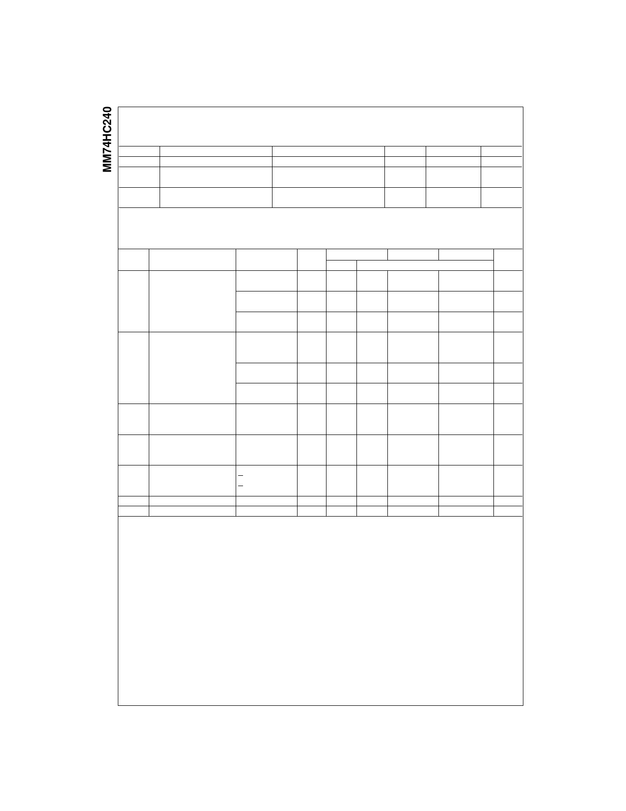
AC Electrical Characteristics
VCC 5V, TA 25qC, tr tf 6 ns
Symbol
Parameter
tPHL, tPLH
tPZH, tPZL
Maximum Propagation Delay
Maximum Enable Delay
to Active Output
tPHZ, tPLZ
Maximum Disable Delay
from Active Output
AC Electrical Characteristics
Conditions
CL 45 pF
RL 1 k:
CL 45 pF
RL 1 k:
CL 5 pF
Typ
Guaranteed Limit Units
12
18
ns
14
28
ns
13
25
ns
VCC 2.0V to 6.0V, CL 50 pF, tr tf 6 ns (unless otherwise specified)
Symbol
Parameter
Conditions
VCC
TA 25qC
Typ
TA 40 to 85qC TA 55 to 125qC
Guaranteed Limits
tPHL, tPLH Maximum Propagation
CL 50 pF
2.0V
55
100
126
149
Delay
CL 150 pF
2.0V
80
150
190
224
CL 50 pF
4.5V
12
20
25
30
CL 150 pF
4.5V
22
30
38
45
CL 50 pF
6.0V
11
17
21
25
CL 150 pF
6.0V
28
26
32
38
tPZH, tPZL Maximum Output Enable
RL 1 k:
TIme
CL 50 pF
2.0V
75
150
189
224
CL 150 pF
2.0V
100
200
252
298
CL 50 pF
4.5V
15
30
38
45
CL 150 pF
4.5V
20
40
50
60
CL 50 pF
6.0V
13
26
32
38
CL 150 pF
6.0V
17
34
43
51
tPHZ, tPLZ Maximum Output Disable
RL 1 k:
2.0V
75
150
189
224
Time
CL 50 pF
4.5V
15
30
38
45
6.0V
13
26
32
38
tTLH, tTHL Maximum Output
Rise and Fall Time
2.0V
4.5V
60
75
90
12
15
18
6.0V
10
13
15
CPD
CIN
COUT
Power Dissipation
(per buffer)
Capacitance (Note 5)
Maximum Input Capacitance
G VIH
G VIL
Maximum Output Capacitance
12
50
5
10
10
10
10
20
20
20
Note 5: CPD determines the no load dynamic power consumption, PD CPD VCC2 f ICC VCC, and the no load dynamic current consumption,
IS CPD VCC f ICC.
Units
ns
ns
ns
ns
ns
ns
ns
ns
ns
ns
ns
ns
ns
ns
ns
ns
ns
ns
pF
pF
pF
pF
www.fairchildsemi.com
4
Share Link: 