ISL97684IRTZ 查看數據表(PDF) - Intersil
零件编号
产品描述 (功能)
生产厂家
ISL97684IRTZ Datasheet PDF : 17 Pages
| |||
ISL97682, ISL97683, ISL97684
Maximum DC Current Setting
The initial brightness should be set by choosing an appropriate
value for RSET. This should be chosen to fix the maximum
possible LED current as shown in Equation 2 for ISL97682 and
Equation 3 for ISL97683 and ISL97684:
ILEDmax
=
-(--8---0----4----)
RSET
(EQ. 2)
ILED1-20mA
ILED2-20mA
ILED3-20mA
ILED4-20mA
ILEDmax
=
-(--4---0----2----)
RSET
(EQ. 3)
DC Current Adjustment
Once RSET is fixed, the LED DC current can be adjusted.
For example, in the 4-channel ISL97684, if the maximum required
LED current (ILED(max)) is 20mA, rearranging Equation 3 yields
Equation 4:
RSET = (402) ⁄ 0.02 = 20.1kΩ
(EQ. 4)
PWM Control
The ISL97682, ISL97683, ISL97684 have high speed 8-bit
digitizers that decode the incoming PWM signal and convert it into
2- 3- or 4- channels of 8-bit PWM current with a phase shift
function that will be described later. During the PWM On period,
the LED peak current is defined by the RSET resistor value. The
average LED current of each channel is controlled by ILEDmax and
the PWM duty cycle in percent shown by Equation 5:
ILED(ave) = ILEDmax × PWM
(EQ. 5)
When the PWM input = 0, all channels are disconnected and the
ILED is guaranteed to be <5µA in this state.
The PWM dimming frequency is adjusted by a resistor at the
RFPWM pin, described in “PWM Dimming Frequency
Adjustment” on page 12.
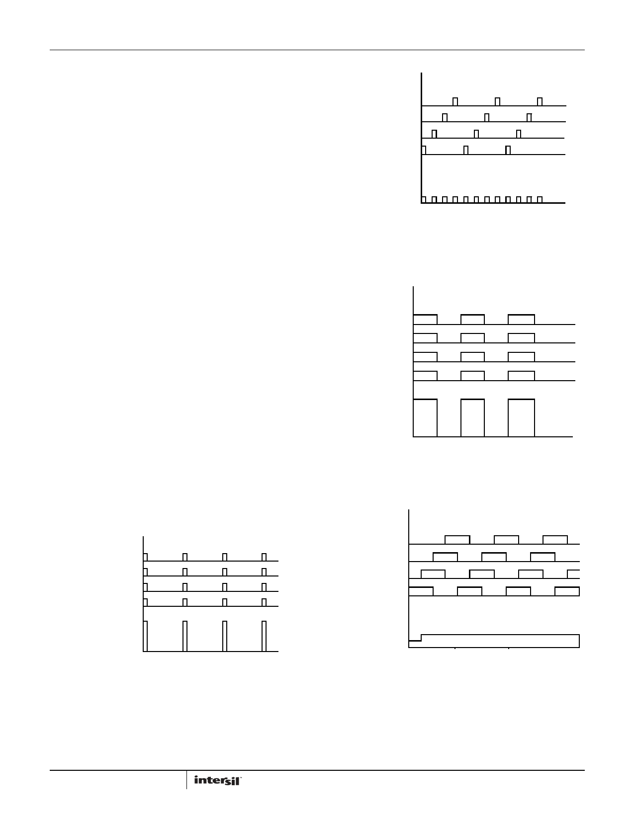
ILED1-20mA
ILED2-20mA
ILED3-20mA
ILED4-20mA
ILED_Total_80mA
5
10
15
TIME (ms)
FIGURE 20. CONVENTIONAL 4-Ch LED DRIVER WITH 10% PWM
DIMMING CHANNEL CURRENT (UPPER) AND TOTAL
CURRENT (LOWER)
ILED_Total_20mA
5
10
TIME (ms)
FIGURE 21. PHASE SHIFT 4-Ch LED DRIVER WITH 10% PWM
DIMMING CHANNEL CURRENT (UPPER) AND TOTAL
CURRENT (LOWER)
ILED4-20mA
ILED3-20mA
ILED2-20mA
ILED1-20mA
ILED_Total_80mA
5
10
TIME (ms)
FIGURE 22. CONVENTIONAL LED DRIVER PWM DIMMING CHANNEL
AND TOTAL CURRENT AT 50% DUTY CYCLE
ILED4-20mA
ILED3-20mA
ILED2-20mA
ILED1-20mA
ILED_Total_40mA
5
10
TIME (ms)
FIGURE 23. EQUAL PHASE SHIFT LED DRIVER PWM DIMMING
CHANNEL AT 50% DUTY CYCLE
11
FN7689.0
March 11, 2011
Share Link: 