HEC40192BT 查看數據表(PDF) - Philips Electronics
零件编号
产品描述 (功能)
生产厂家
HEC40192BT Datasheet PDF : 9 Pages
| |||
Philips Semiconductors
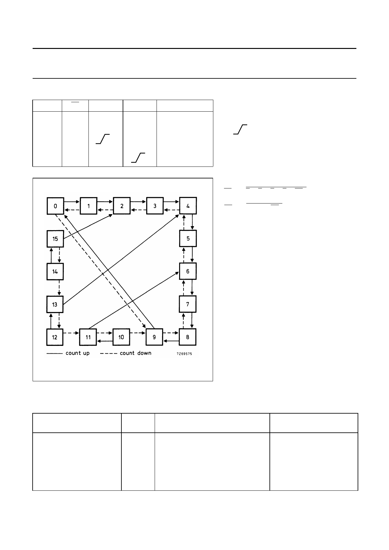
4-bit up/down decade counter
FUNCTION TABLE
MR
PL
CPU
H
X
X
L
L
X
L
H
L
H
H
CPD
MODE
X
reset (asyn.)
X
parallel load
H
count-up
count-down
Product specification
HEF40192B
MSI
Notes
1. H = HIGH state (the more positive voltage)
L = LOW state (the less positive voltage)
X = state is immaterial
= positive-going transition
Logic equations for terminal count:
TCD = O0 ⋅ O1 ⋅ O2 ⋅ O3 ⋅ CPD
TCU = O0 ⋅ O3 ⋅ CPU
Fig.5 State diagram.
AC CHARACTERISTICS
VSS = 0 V; Tamb = 25 °C; input transition times ≤ 20 ns
Dynamic power
dissipation per
package (P)
VDD
V
TYPICAL FORMULA FOR P (µW)
5
550 fi + ∑(foCL) × VDD2
10
2400 fi + ∑(foCL) × VDD2
15
6500 fi + ∑(foCL) × VDD2
where
fi = input freq. (MHz)
fo = output freq. (MHz)
CL = load capacitance (pF)
∑ (foCL) = sum of outputs
VDD = supply voltage (V)
January 1995
5
Share Link: 