EL1509CS-T7 查看數據表(PDF) - Intersil
零件编号
产品描述 (功能)
生产厂家
EL1509CS-T7 Datasheet PDF : 10 Pages
| |||
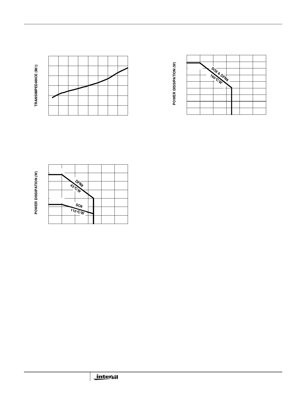
Typical Performance Curves
EL1509
3
2.5
2
1.5
1
0.5
0
-50 -25
0 25 50 75 100 125 150
TEMPERATURE (°C)
FIGURE 25. TRANSIMEDANCE vs TEMPERATURE
JEDEC JESD51-7 HIGH EFFECTIVE THERMAL
CONDUCTIVITY (4-LAYER) TEST BOARD (DFN EXPOSED
DIEPAD SOLDERED TO PCB PER JESD51-5)
3.5
3 2.907W
2.5
2
43°CD/FWN8
1.5 1.136W
1
0.5
SO8
110°C/W
0
0
25
50
75 85 100 125 150
AMBIENT TEMPERATURE (°C)
FIGURE 27. PACKAGE POWER DISSIPATION vs AMBIENT
TEMPERATURE
Applications Information
Product Description
The EL1509 is a dual operational amplifier designed for
customer premise line driving in DMT ADSL solutions. It is a
dual current mode feedback amplifier with low distortion
while drawing moderately low supply current. It is built using
Elantec's proprietary complimentary bipolar process and is
offered in industry standard pin-outs. Due to the current
feedback architecture, the EL1509 closed-loop 3dB
bandwidth is dependent on the value of the feedback
resistor. First the desired bandwidth is selected by choosing
the feedback resistor, RF, and then the gain is set by picking
the gain resistor, RG. The curves at the beginning of the
Typical Performance Curves section show the effect of
varying both RF and RG. The 3dB bandwidth is somewhat
dependent on the power supply voltage.
JEDEC JESD51-3 AND SEMI G42-88 (SINGLE
LAYER) TEST BOARD
0.9
0.8
0.7 781mW
0.6
0.5
1S6O0°8C&/WDFN8
0.4
0.3
0.2
0.1
0
0
25
50
75 85 100 125 150
AMBIENT TEMPERATURE (°C)
FIGURE 26. PACKAGE POWER DISSIPATION vs AMBIENT
TEMPERATURE
Power Supply Bypassing and Printed Circuit
Board Layout
As with any high frequency device, good printed circuit
board layout is necessary for optimum performance. Ground
plane construction is highly recommended. Lead lengths
should be as short as possible, below ¼”. The power supply
pins must be well bypassed to reduce the risk of oscillation.
A 1.0µF tantalum capacitor in parallel with a 0.01µF ceramic
capacitor is adequate for each supply pin.
For good AC performance, parasitic capacitances should be
kept to a minimum, especially at the inverting input. This
implies keeping the ground plane away from this pin. Carbon
resistors are acceptable, while use of wire-wound resistors
should not be used because of their parasitic inductance.
Similarly, capacitors should be low inductance for best
performance.
7
FN7015.2
March 26, 2007
Share Link: 