ADUM7442CRQZ-RL7 查看數據表(PDF) - Analog Devices
零件编号
产品描述 (功能)
生产厂家
ADUM7442CRQZ-RL7 Datasheet PDF : 20 Pages
| |||
ADuM7440/ADuM7441/ADuM7442
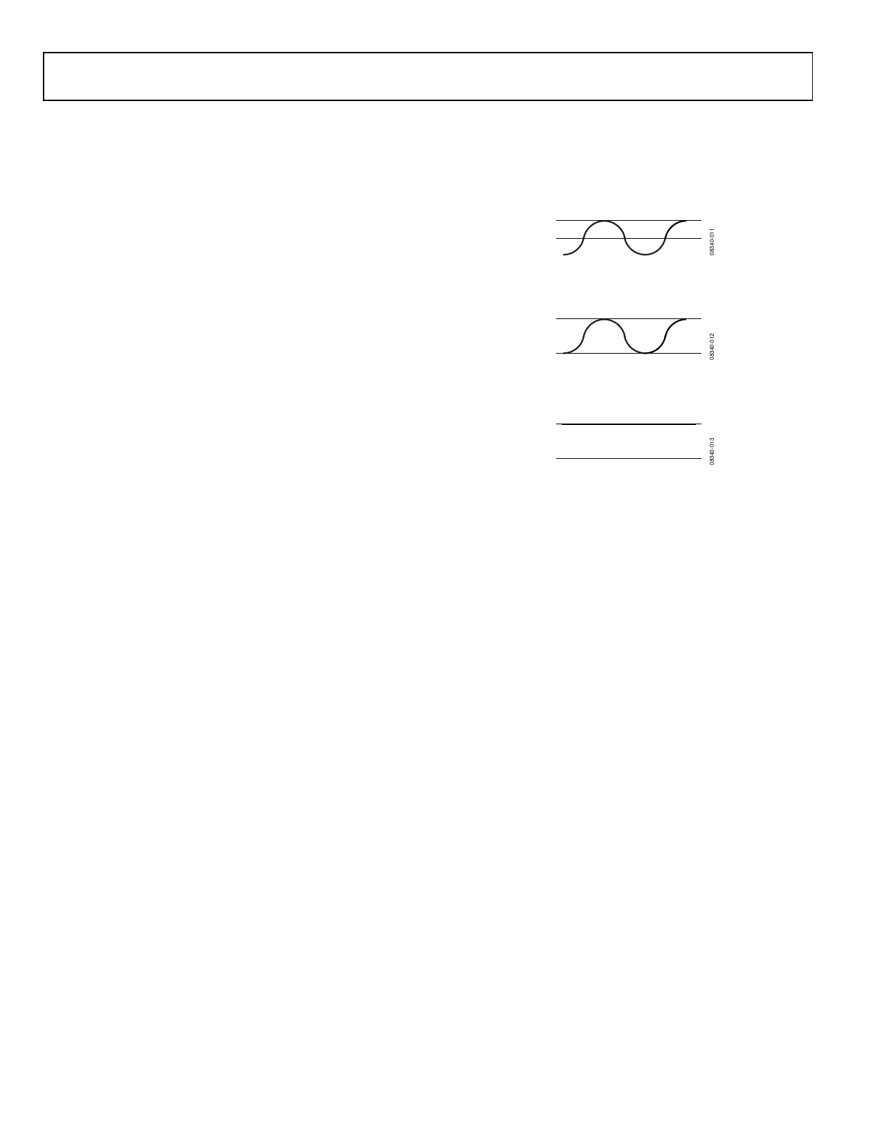
The insulation lifetime of the ADuM744x depends on the
voltage waveform type imposed across the isolation barrier.
The iCoupler insulation structure degrades at different rates
depending on whether the waveform is bipolar ac, unipolar
ac, or dc. Figure 20, Figure 21, and Figure 22 illustrate these
different isolation voltage waveforms.
Bipolar ac voltage is the most stringent environment. The goal
of a 50-year operating lifetime under the ac bipolar condition
determines the Analog Devices recommended maximum
working voltage.
In the case of unipolar ac or dc voltage, the stress on the insu-
lation is significantly lower. This allows operation at higher
working voltages while still achieving a 50-year service life.
The working voltages listed in Table 18 can be applied while
maintaining the 50-year minimum lifetime provided the voltage
conforms to either the unipolar ac or dc voltage case. Any cross-
insulation voltage waveform that does not conform to Figure 21
or Figure 22 should be treated as a bipolar ac waveform, and its
peak voltage should be limited to the 50-year lifetime voltage
value listed in Table 18.
Note that the voltage presented in Figure 21 is shown as sinusoidal
for illustration purposes only. It is meant to represent any voltage
waveform varying between 0 V and some limiting value. The
limiting value can be positive or negative, but the voltage cannot
cross 0 V.
RATED PEAK VOLTAGE
0V
Figure 20. Bipolar AC Waveform
RATED PEAK VOLTAGE
0V
Figure 21. Unipolar AC Waveform
RATED PEAK VOLTAGE
0V
Figure 22. DC Waveform
Rev. B | Page 16 of 20
Share Link: 