ADT7485A 查看數據表(PDF) - Analog Devices
零件编号
产品描述 (功能)
生产厂家
ADT7485A Datasheet PDF : 16 Pages
| |||
ADT7485A
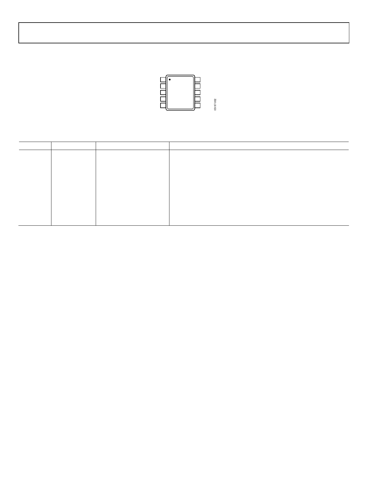
PIN CONFIGURATION AND FUNCTIONAL DESCRIPTIONS
VCC 1
10 SST
GND 2 ADT7485A 9 ADD
D1+ 3 TOP VIEW 8 2.5V
(Not to Scale)
D1– 4
7 VCCP
12V 5
6 5V
Figure 2. 10-Lead MSOP
Table 4. Pin Function Descriptions
Pin No.
Mnemonic
Type
1
VCC
Power supply
2
GND
Ground
3
D1+
Analog input
4
D1−
Analog input
5
12V
Analog input
6
5V
Analog input
7
VCCP
Analog input
8
2.5V
Analog input
9
ADD
Digital input
10
SST
Digital input/output
Description
3.3 V ± 10%. VCC is also monitored through this pin.
Ground Pin.
Positive Connection to Remote 1 Temperature Sensor.
Negative Connection to Remote 1 Temperature Sensor.
12 V Supply Monitor.
5 V Supply Monitor.
Processor Core Voltage Monitor.
2.5 V Supply Monitor.
SST Address Select.
SST Bidirectional Data Line.
Rev. 0 | Page 6 of 16
Share Link: 