74HC194D 查看數據表(PDF) - Philips Electronics
零件编号
产品描述 (功能)
生产厂家
74HC194D Datasheet PDF : 11 Pages
| |||
Philips Semiconductors
4-bit bidirectional universal shift register
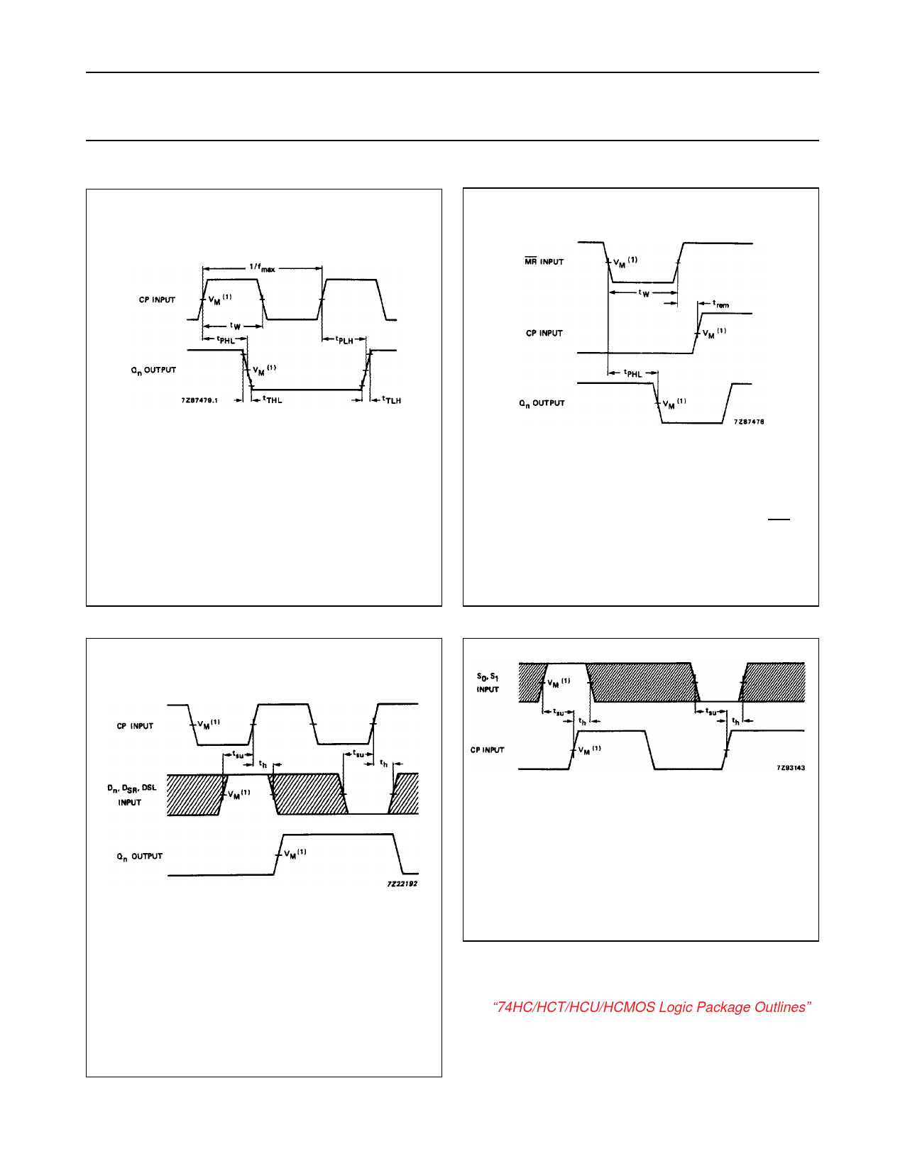
AC WAVEFORMS
Product specification
74HC/HCT194
(1) HC : VM = 50%; VI = GND to VCC.
HCT: VM = 1.3 V; VI = GND to 3 V.
Fig.7
Waveforms showing the clock (CP) to
output (Qn) propagation delays, the clock
pulse width, the output transition times and
the maximum clock frequency.
(1) HC : VM = 50%; VI = GND to VCC.
HCT: VM = 1.3 V; VI = GND to 3 V.
Fig.8
Waveforms showing the master reset (MR)
pulse width, the master reset to output (Qn)
propagation delays and the master reset to
clock (CP) removal time.
The shaded areas indicate when the input is permitted to
change for predictable output performance.
(1) HC : VM = 50%; VI = GND to VCC.
HCT: VM = 1.3 V; VI = GND to 3 V.
Fig.9 Waveforms showing the set-up and hold
times from the data inputs (Dn, DSR and
DSL) to the clock (CP).
The shaded areas indicate when the input is permitted to
change for predictable output performance.
(1) HC : VM = 50%; VI = GND to VCC.
HCT: VM = 1.3 V; VI = GND to 3 V.
Fig.10 Waveforms showing the set-up and hold
times from the mode control inputs (Sn) to
the clock input (CP).
PACKAGE OUTLINES
See “74HC/HCT/HCU/HCMOS Logic Package Outlines”.
December 1990
10
Share Link: 