M54HC4066K1 查看數據表(PDF) - STMicroelectronics
零件编号
产品描述 (功能)
生产厂家
M54HC4066K1 Datasheet PDF : 11 Pages
| |||
M54HC4066
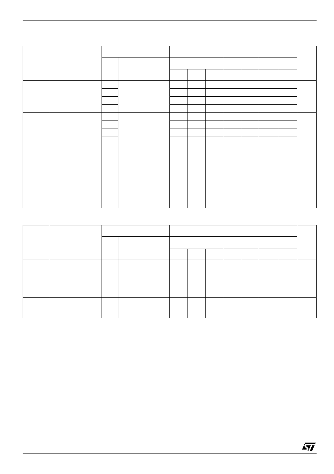
Table 6: AC Electrical Characteristics (CL = 50 pF, Input tr = tf = 6ns)
Test Condition
Symbol
Parameter
VCC
(V)
ΦI/O Phase Difference 2.0
Between Input and 4.5
Output
9.0
12.0
tPZL Output Enable Time 2.0
tPZH
4.5
9.0
RL = 1KΩ
12.0
tPLZ Output Disable
2.0
tPHZ Time
4.5
9.0
RL = 1KΩ
12.0
Maximum Control
Input Frequency
2.0
4.5
9.0
12.0
RL = 1KΩ
CL = 15 pF
VOUT = 1/2 VCC
Table 7: Capacitive Characteristics
Value
TA = 25°C
-40 to 85°C -55 to 125°C Unit
Min.
Typ. Max. Min. Max.
10 50
65
4 10
13
3
8
10
3
7
9
18 100
125
8 20
25
6 12
22
6 12
18
20 115
145
10 23
29
8 20
25
8 18
22
30
30
30
30
Min.
Max.
75
15
13
10
150
30
27
25
175
35
30
27
ns
ns
ns
MHz
Test Condition
Value
Symbol
Parameter
VCC
(V)
CIN
CI/O
CIOS
CPD
Input Capacitance
Switch Terminal
Capacitance
Feed Through
Capacitance
Power Dissipation
Capacitance
(note 1)
TA = 25°C
-40 to 85°C -55 to 125°C Unit
Min. Typ. Max. Min. Max. Min. Max.
5 10
10
10 pF
6
pF
0.5
pF
15
pF
1) CPD is defined as the value of the IC’s internal equivalent capacitance which is calculated from the operating current consumption without
load. (Refer to Test Circuit). Average operating current can be obtained by the following equation. ICC(opr) = CPD x VCC x fIN + ICC
4/11
Share Link: 