AD7606BSTZ 查看數據表(PDF) - Analog Devices
零件编号
产品描述 (功能)
生产厂家
AD7606BSTZ Datasheet PDF : 36 Pages
| |||
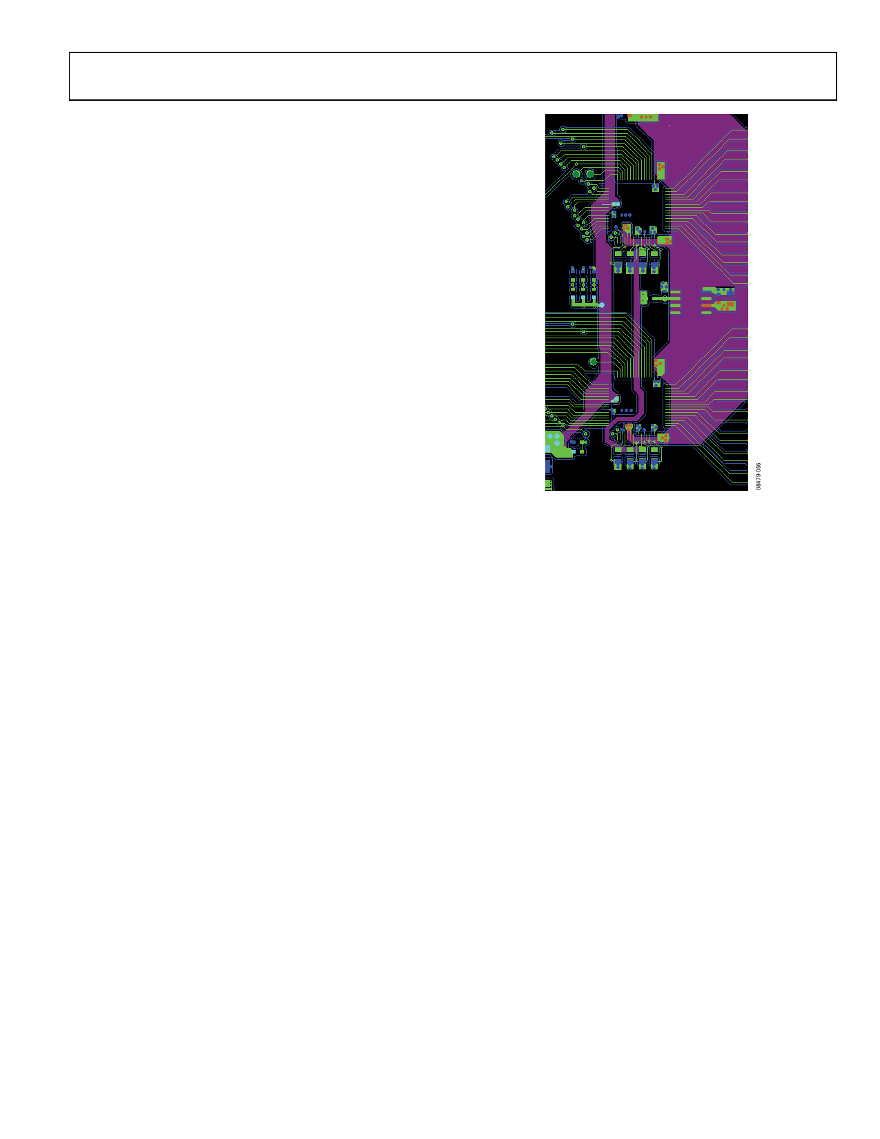
To ensure good device-to-device performance matching in
a system that contains multiple AD7606/AD7606-6/AD7606-4
devices, a symmetrical layout between the AD7606/AD7606-6/
AD7606-4 devices is important.
Figure 64 shows a layout with two AD7606/AD7606-6/AD7606-4
devices. The AVCC supply plane runs to the right of both devices,
and the VDRIVE supply track runs to the left of the two devices.
The reference chip is positioned between the two devices, and
the reference voltage track runs north to Pin 42 of U1 and south
to Pin 42 of U2. A solid ground plane is used.
These symmetrical layout principles can also be applied to a system
that contains more than two AD7606/AD7606-6/AD7606-4
devices. The AD7606/AD7606-6/AD7606-4 devices can be placed
in a north-south direction, with the reference voltage located
midway between the devices and the reference track running in
the north-south direction, similar to Figure 64.
AD7606/AD7606-6/AD7606-4
AVCC
U2
U1
Figure 64. Layout for Multiple AD7606 Devices—Top Layer and
Supply Plane Layer
Rev. 0 | Page 33 of 36
Share Link: 