SC28L194A1BE 查看數據表(PDF) - Philips Electronics
零件编号
产品描述 (功能)
生产厂家
SC28L194A1BE Datasheet PDF : 52 Pages
| |||
Philips Semiconductors
Quad UART for 3.3V and 5V supply voltage
Preliminary specification
SC28L194
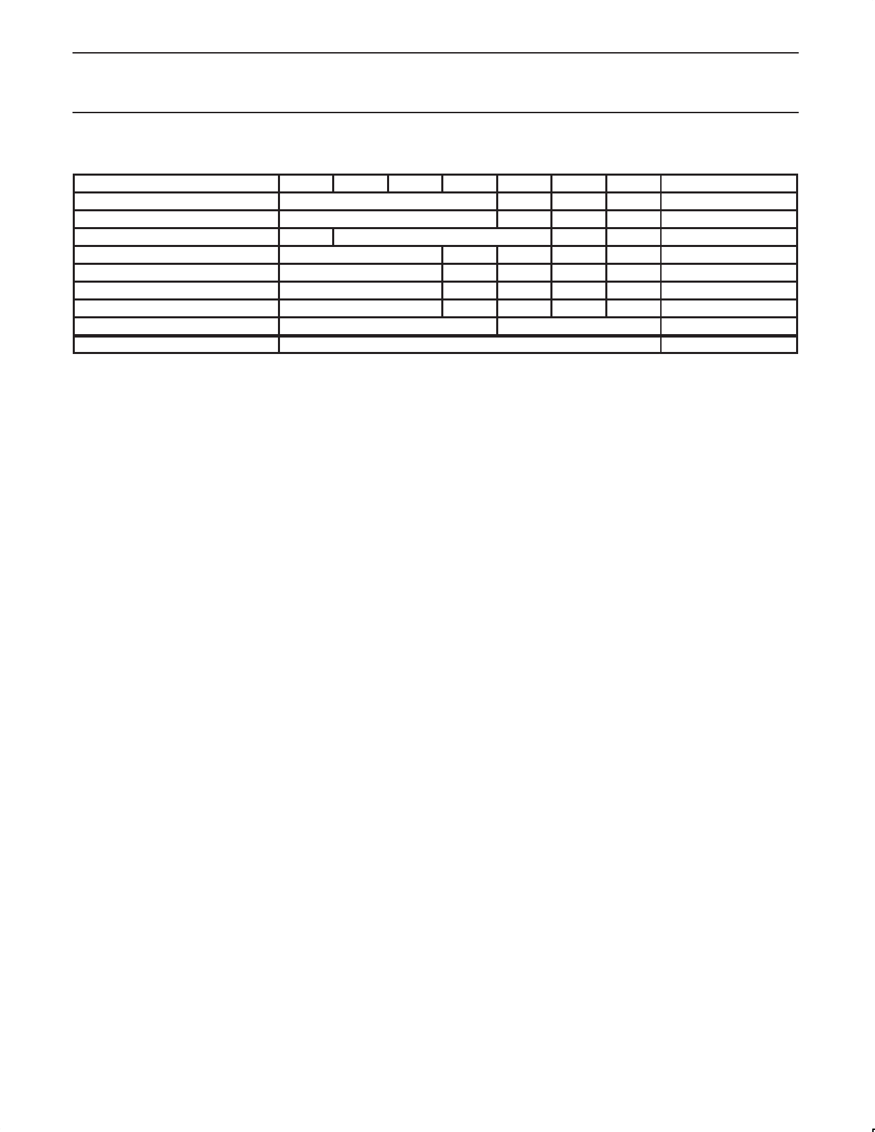
Table 1. Interrupt Arbitration Priority
ÁÁÁÁÁÁÁÁÁÁÁÁÁÁÁÁÁÁÁÁÁÁÁÁÁÁÁÁÁÁÁÁÁÁ Type
B9
B8
B7
B6
ÁÁÁÁÁÁÁÁÁÁÁÁÁÁÁÁÁÁÁÁÁÁÁÁÁÁÁÁÁÁÁÁÁÁ Receiver w/o error
RxFIFO Byte Count -1
ÁÁÁÁÁÁÁÁÁÁÁÁÁÁÁÁÁÁÁÁÁÁÁÁÁÁÁÁÁÁÁÁÁÁ Receiver w/ error
RxFIFO Byte Count -1
ÁÁÁÁÁÁÁÁÁÁÁÁÁÁÁÁÁÁÁÁÁÁÁÁÁÁÁÁÁÁÁÁÁÁ Transmitter
0
TxFIFO Byte Count -1
Change of Break
Programmed Field
0
ÁÁÁÁÁÁÁÁÁÁÁÁÁÁÁÁÁÁÁÁÁÁÁÁÁÁÁÁÁÁÁÁÁÁ Change of State
Programmed Field
0
ÁÁÁÁÁÁÁÁÁÁÁÁÁÁÁÁÁÁÁÁÁÁÁÁÁÁÁÁÁÁÁÁÁÁ Xon/Xoff
Programmed Field
0
ÁÁÁÁÁÁÁÁÁÁÁÁÁÁÁÁÁÁÁÁÁÁÁÁÁÁÁÁÁÁÁÁÁÁ Address Recognition
Programmed Field
0
ÁÁÁÁÁÁÁÁÁÁÁÁÁÁÁÁÁÁÁÁÁÁÁÁÁÁÁÁÁÁÁÁÁÁ Receiver Watch-dog
RxFIFO Byte Count -1
ÁÁÁÁÁÁÁÁÁÁÁÁÁÁÁÁÁÁÁÁÁÁÁÁÁÁÁÁÁÁÁÁÁÁÁÁÁÁÁÁÁÁÁÁÁÁÁÁÁÁÁÁÁÁÁÁÁÁÁÁÁÁÁÁÁÁÁÁ Threshold
Bits 6:0 of Interrupt Control Register
B5
B4
0
0
1
0
0
0
1
1
1
1
1
0
1
As RxFIFO Above
B3
1
1
0
0
0
1
1
Bits 2:0
Channel No
Channel No
Channel No
Channel No
Channel No
Channel No
Channel No
Channel No
000
Note several characteristics of the above table in bits 6:3. These bits
the DSR (Data Set Ready) signal from the modem. In this case its
contain the identification of the bidding source as indicated below:
arbitration value should be high. Once the DSR is recognized then
x001 Receiver without error
its arbitration value could be reduced or turned off.
x101
xx00
0010
0110
0111
0011
Receiver with error
Transmitter
Change of Break
Change of State on I/O Ports
Xon/Xoff Event
Address Recognition
The codes form bits 6:3 drive part of the interrupt vector modification
and the Global Interrupt Type Register. The codes are unique to
each source type and Identify them completely. The channel
numbering progresses from “a” to “d” as the binary numbers 000 to
011 and identify the interrupting channel uniquely. As the channels
arbitrate “d” will have the highest bidding value and “a” the lowest
There is a single arbiter interrupt number that is not associated with
any of the UART channels. It is the “Threshold Value” and is
comprised of 7 bits from the Interrupt Control Register, ICR, and
three zeros in the channel field. It is only when one or more of the
enabled interrupt sources generates a arbitration value larger
than the threshold value that the IRQN will be asserted. When
the threshold bidding value is larger than any other bidding value
then the IRQN will be withdrawn. In this condition, when nothing is
interrupting, the CIR will be loaded with zeros if the IRQN is
asserted or “Update CIR” command is issued. Because the
channels are numbered from 0 to 3 ( A to D) channel 3 will win the
bid when all other parts of the bid are equal.
Note that the transmitter byte count is off-set from that of the
receiver by one bit. This is to give the receiver more authority in the
arbitration since and over-run receiver corrupts the message but an
under-run transmitter is not harmful. This puts some constraints on
how the threshold value is selected. If a threshold is chosen that has
its MSB set to one then a transmitter can never generate an
interrupt! Of course the counter point to this is the desire to set the
interrupt threshold high so interrupts occur only when a maximum or
near maximum number of characters may be transferred.
To give some control over this dilemma control bits have been
provided in the MR0 and MR2 registers of each channel to
individually control when a receiver or transmitter may interrupt. The
use of these bits will prevent a receiver or a transmitter from
entering the arbitration process even though its FIFO fill level is
above that indicated by the threshold value set. The bits in the MR0
and MR2 register are named TxINT (MR0[5:4]) and RxINT
(MR2[3:2])
Watch-Dog Timer
The watch-dog is included in the table above to show that it affects
the arbitration. It does not have an identity of its own. A barking
watch-dog will prevent any other source type from entering the
arbitration process except enabled receivers. The threshold is
effectively set to zero when any watch-dog times out. The receivers
arbitrate among them selves and the one with the highest fill level
will win the process. Note that the receiver wining the bid may not be
the one that caused the watch-dog to bark.
The fields labeled “Programmed Field” are the contents of the
Bidding Control Registers, BCRs, for these sources. Setting these
bits to high values can elevate the interrupt importance of the
sources they represent to values almost as high as a full receiver.
For example a COS event may be very important when it represents
Note: Based on the xx00 coding for the transmitter (as shown
in Table 1 above), a transmitter will not win a bid in the situation
where the Count Field = 0 unless the threshold value is equal to
or less than 0000011. A single empty slot is left in the TxFIFO,
or a single filled slot in the RxFIFO will bid with a byte count
value of zero.
MODES OF OPERATION
Major Modes
Four major modes of operation (normal, auto echo, local loop back
and remote loop back) are provided and are controlled by MR2[7:6].
Three of these may be considered diagnostic. See the MR2 register
description.
The normal mode is the usual mode for data I/O operation. Most
reception and transmission will use the normal mode.
In the auto echo mode, the transmitter automatically re-transmits
any character captured by the channel’s receiver. The receiver 1x
clock is used for the transmitter. This mode returns the received
data back to the sending station one bit time delayed from its
departure. Receiver to host communication is normal. Host to
transmitter communication has no meaning.
In the local loop back mode (used for diagnostic purposes) the
transmitter is internally connected to the receiver input. The
transmitter 1x clock used for the receiver. The RxD input pin is
ignored and the transmitter TxD output pin is held high. This
configuration allows the transmitter to send data to the receiver
without any external parameters to affect the transmission of data.
All status bits, interrupt conditions and processor interface operate
normally. It is recommended that this mode be used when
initially verifying processor to UART interface. The
1998 Sep 21
12
Share Link: 