FSAM15SH60 查看數據表(PDF) - Fairchild Semiconductor
零件编号
产品描述 (功能)
生产厂家
FSAM15SH60 Datasheet PDF : 16 Pages
| |||
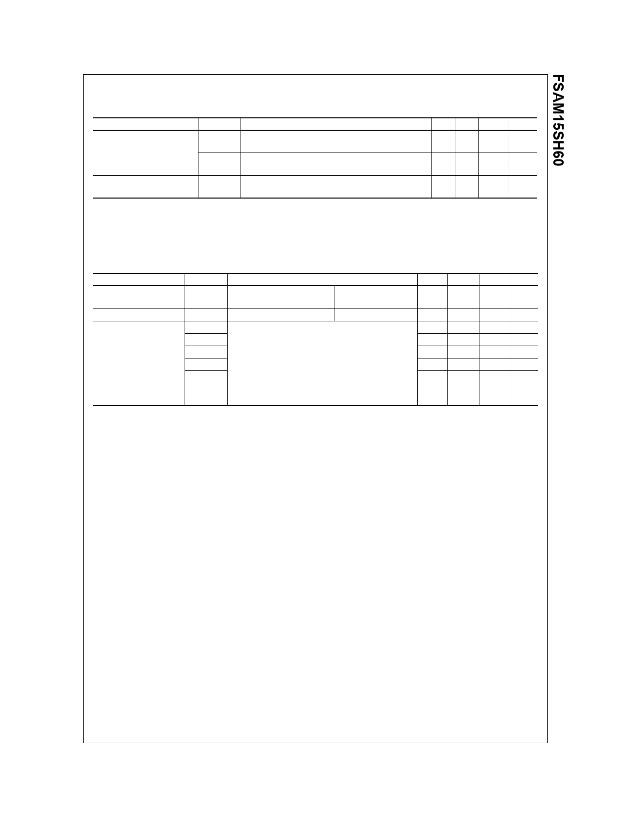
Absolute Maximum Ratings
Thermal Resistance
Item
Junction to Case Thermal
Resistance
Symbol
Condition
Rth(j-c)Q Each IGBT under Inverter Operating Condition
Rth(j-c)F Each FWDi under Inverter Operating Condition
Min. Typ. Max. Unit
-
- 2.71 °C/W
-
- 3.71 °C/W
Contact Thermal
Resistance
Rth(c-h) Ceramic Substrate (per 1 Module)
Thermal Grease Applied (Note 3)
-
- 0.06 °C/W
Note:
2. For the measurement point of case temperature(TC), please refer to Fig. 2.
3. The thickness of thermal grease should not be more than 100um.
Electrical Characteristics (TJ = 25°C, Unless Otherwise Specified)
Inverter Part
Item
Collector - Emitter
Saturation Voltage
FWDi Forward Voltage
Switching Times
Collector -Emitter
Leakage Current
Symbol
VCE(SAT)
VFM
tON
tC(ON)
tOFF
tC(OFF)
trr
ICES
Condition
VCC = VBS = 15V
VIN = 0V
IC = 15A, TJ = 25°C
VIN = 5V
IC = 15A, TJ = 25°C
VPN = 300V, VCC = VBS = 15V
IC = 15A, TJ = 25°C
VIN = 5V ↔ 0V, Inductive Load
(High, Low-side)
(Note 4)
VCE = VCES, TJ = 25°C
Min.
-
-
-
-
-
-
-
-
Typ.
-
-
0.39
0.12
0.53
0.16
0.1
-
Max. Unit
2.8
V
2.5
V
-
us
-
us
-
us
-
us
-
us
250 uA
Note:
4. tON and tOFF include the propagation delay time of the internal drive IC. tC(ON) and tC(OFF) are the switching time of IGBT itself under the given gate driving condition
internally. For the detailed information, please see Fig. 4.
©2003 Fairchild Semiconductor Corporation
Rev. D, August 2003
Share Link: 