ZL2106ALCFTK Просмотр технического описания (PDF) - Renesas Electronics
Номер в каталоге
Компоненты Описание
производитель
ZL2106ALCFTK Datasheet PDF : 29 Pages
| |||
ZL2106
The soft-start delay period begins when the EN pin is asserted
and ends when the delay time expires. The soft-start delay period
is set using the SS pin. Precise ramp delay timing mode reduces
the delay time variations and is available when the appropriate
bit in the MISC_CONFIG register had been set. Please refer to
Application Note AN2033 for details.
The soft-start ramp timer enables a precisely controlled ramp to
the nominal VOUT value that begins once the delay period has
expired. The ramp-up is guaranteed monotonic and its slope may
be precisely set using the SS pin. Using the pin-strap method, the
soft-start delay and ramp times can be set to one of three
standard values according to Table 5.
TABLE 5. SOFT-START DELAY AND RAMP SETTINGS
SS PIN SETTING
DELAY AND
RAMP TIME
(ms)
UVLO
LOW
2
OPEN
5
7.5V
HIGH
10
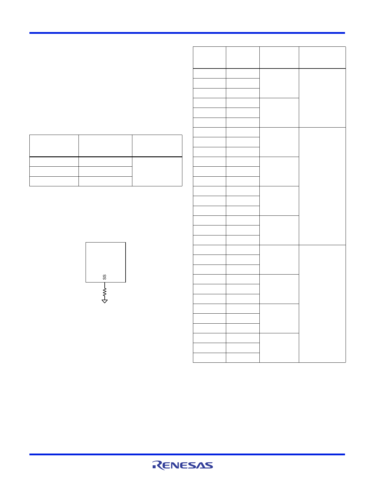
If the desired soft-start delay and ramp times are not one of the
values listed in Table 5, the times can be set to a custom value by
connecting a resistor from the SS pin to SGND using the
appropriate resistor value from Table 6. The value of this resistor
is measured upon start-up or Restore and will not change if the
resistor is varied after power has been applied to the ZL2106
(see Figure 15).
ZL
RSS
FIGURE 15. SS PIN RESISTOR CONNECTIONS
The soft-start delay and ramp times can also be set to custom
values via the I2C/SMBus interface. When the SS delay time is
set to 0ms, the device will begin its ramp-up after the internal
circuitry has initialized (~2ms). When the soft-start ramp period
is set to 0ms, the output will ramp up as quickly as the output
load capacitance and loop settings will allow. It is generally
recommended to set the soft-start ramp to a value greater than
500µs to prevent inadvertent fault conditions due to excessive
inrush current.
RSS
(k)
10
11
12.1
13.3
14.7
16.2
17.8
19.6
21.5
23.7
26.1
28.7
31.6
34.8
38.3
42.2
46.4
51.1
56.2
61.9
68.1
75
82.5
90.9
100
110
121
133
147
162
TABLE 6. DELAY AND RAMP CONFIGURATION
DELAY
TIME
(ms)
RAMP
TIME
(ms)
UVLO
(V)
5
10
5
20
4.5
5
10
10
20
5
10
2
20
5
10
5
20
5.5
5
10
10
20
5
10
20
20
5
10
2
20
5
10
5
20
7.5
5
10
10
20
5
10
20
20
FN6852 Rev 6.00
February 20, 2013
Page 14 of 29
Share Link: 