BLV920 Просмотр технического описания (PDF) - Philips Electronics
Номер в каталоге
Компоненты Описание
производитель
BLV920 Datasheet PDF : 12 Pages
| |||
Philips Semiconductors
UHF power transistor
Product specification
BLV920
CHARACTERISTICS
Tj = 25 °C unless otherwise specified.
SYMBOL
PARAMETER
V(BR)CBO collector-base breakdown
voltage
V(BR)CEO collector-emitter breakdown
voltage
V(BR)EBO emitter-base breakdown
voltage
ICES
collector leakage current
hFE
DC current gain
Cc
collector capacitance
Cre
feedback capacitance
CONDITIONS
open emitter; IC = 15 mA
open base; IC = 30 mA
open collector; IE = 0.6 mA
VBE = 0; VCE = 28 V
VCE = 10 V; IC = 1 A; note 1
VCB = 26 V; IE = ie = 0; f = 1 MHz
VCE = 26 V; IC = 0; f = 1 MHz
Note
1. Measured under pulsed conditions: tp ≤ 500 µs; δ ≤ 0.01.
MIN.
70
30
3
−
30
−
−
TYP.
−
−
−
−
−
17
11
MAX. UNIT
−
V
−
V
−
V
1.5
mA
120
−
pF
−
pF
handbook1, 0h0alfpage
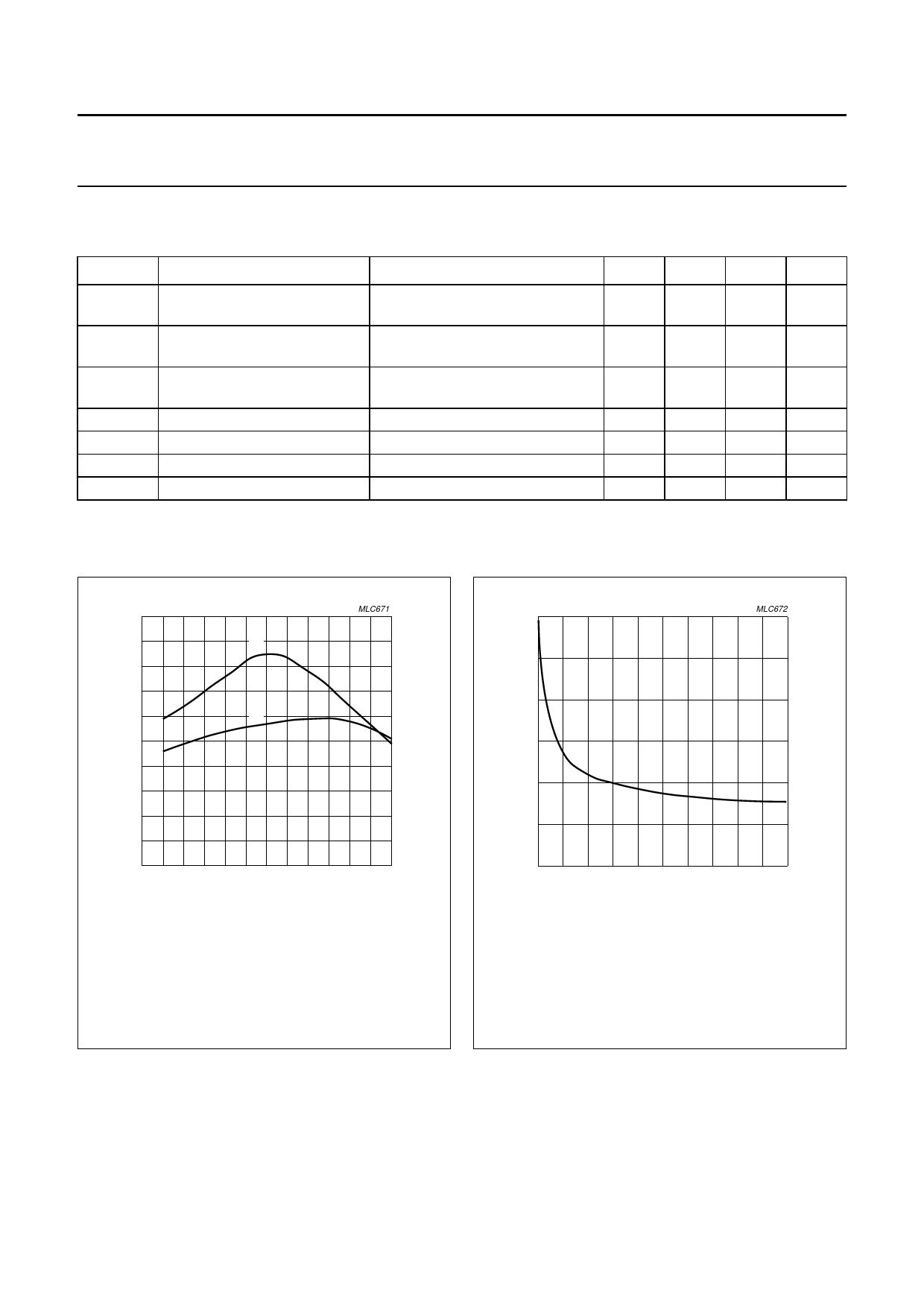
h FE
(1)
80
MLC671
60
(2)
40
20
0
0
1
2
3
4
5
6
I C (A)
Measured under pulsed conditions; tp ≤ 500 µs; δ ≤ 0.01.
(1) VCE = 26 V.
(2) VCE = 10 V.
Fig.4 DC current gain as a function of collector
current; typical values.
60
handbook, halfpage
Cc
(pF)
40
MLC672
20
0
0
10
20
30
40
50
VCB (V)
IE = ie = 0; f = 1 MHz.
Fig.5 Collector capacitance as a function of
collector-base voltage; typical values.
1997 Nov 17
4
Share Link: 