MPC7410RX500PD Просмотр технического описания (PDF) - Unspecified
Номер в каталоге
Компоненты Описание
производитель
MPC7410RX500PD Datasheet PDF : 56 Pages
| |||
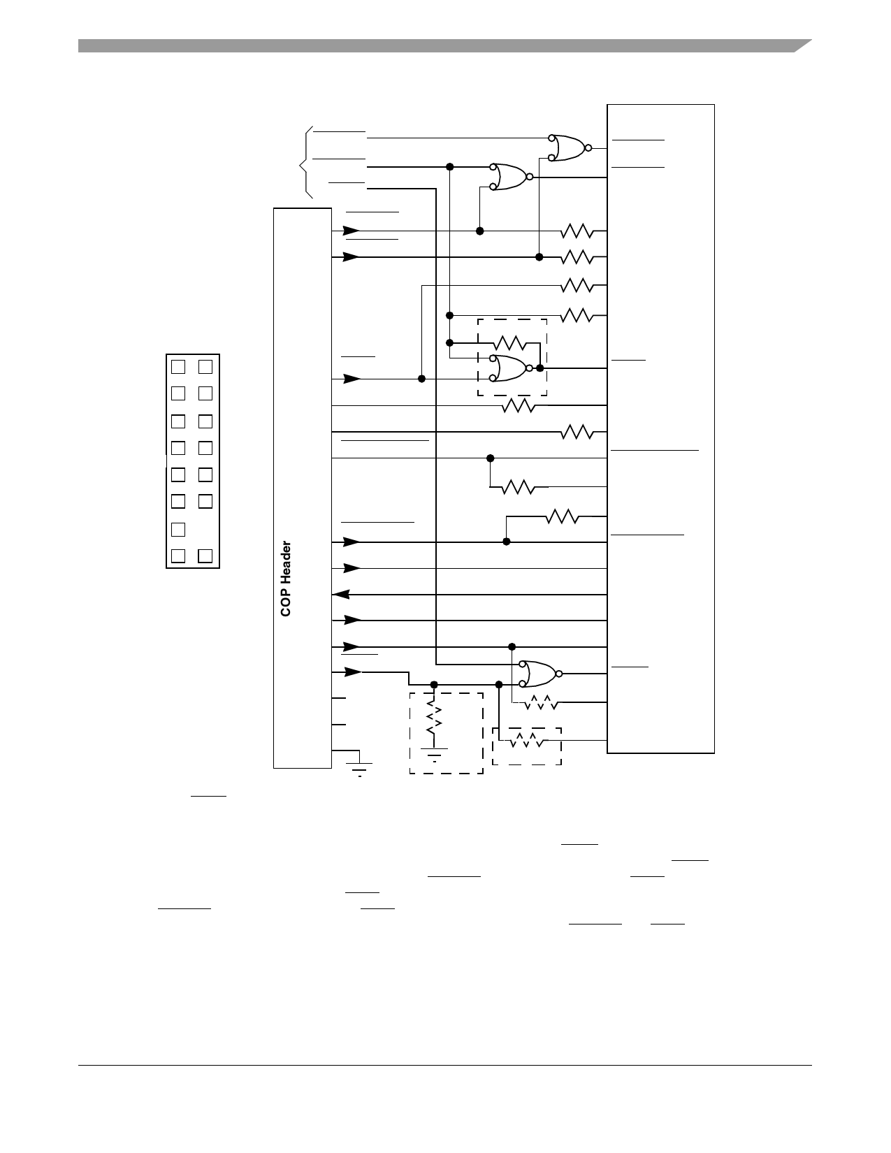
System Design Information
From Target
Board Sources
(if any)
SRESET
HRESET
QACK
HRESET
13
SRESET
11
SRESET
HRESET 6
0Ω5
10 kΩ
10 kΩ
10 kΩ
10 kΩ
OVDD
OVDD
OVDD
OVDD
12
34
56
78
9 10
11 12
13
KEY
No Pin
15 16
COP Connector
Physical Pin Out
4
6
51
15
Key
14 2
8
9
1
3
7
2
10
12
16
TRST
VDD_SENSE
CHKSTP_OUT
CHKSTP_IN
TMS
TDO
TDI
TCK
QACK
NC
NC
2 kΩ 3
TRST 6
2 kΩ 10 kΩ
10 kΩ
10 kΩ
OVDD
OVDD
CHKSTP_OUT
OVDD
OVDD
CHKSTP_IN
TMS
TDO
TDI
TCK
QACK
10 kΩ
10 kΩ 4
OVDD
OVDD
Notes:
1. RUN/STOP, normally found on pin 5 of the COP header, is not implemented on the MPC7410. Connect
pin 5 of the COP header to OVDD with a 10-kΩ pull-up resistor.
2. Key location; pin 14 is not physically present on the COP header.
3. Component not populated. Populate only if debug tool does not drive QACK.
4. Populate only if debug tool uses an open-drain type output and does not actively negate QACK.
5. If the JTAG interface is implemented, connect HRESET from the target source to TRST from the COP
header though an AND gate to TRST of the part. If the JTAG interface is not implemented, connect
HRESET from the target source to TRST of the part through a 0-Ω isolation resistor.
6. The COP port and target board should be able to independently assert HRESET and TRST to the pro-
cessor in order to fully control the processor as shown above.
Figure 25. COP Connector Diagram
MPC7410 RISC Microprocessor Hardware Specifications, Rev. 6.1
Freescale Semiconductor
41
Share Link: 