M74HC540C1R Просмотр технического описания (PDF) - STMicroelectronics
Номер в каталоге
Компоненты Описание
производитель
M74HC540C1R
STMicroelectronics
M74HC540C1R Datasheet PDF : 12 Pages
| |||
M54/M74HC540/541
AC ELECTRICAL CHARACTERISTICS (CL = 50 pF, Input tr = tf = 6 ns)
Symbol
Parameter
Test Conditions
VCC CL
(V) (pF)
TA = 25 oC
54HC and 74HC
Value
-40 to 85 oC -55 to 125 oC Unit
74HC
54HC
Min. Typ. Max. Min. Max. Min. Max.
tTLH Output Transition 2.0
tTHL Time
4.5 50
25 60
75
90
7
12
19
18
ns
6.0
6
10
13
15
tPLH Propagation
tPHL Delay Time
2.0
4.5 50
40 85
10 17
105
130
21
26
ns
6.0
9
14
18
22
2.0
4.5 150
56 115
145
175
14 23
29
35
ns
6.0
12 20
25
30
tPZL Output Enable
2.0
47 110
140
165
tPZH Time
4.5 50 RL = 1KΩ
13 22
28
33
ns
6.0
11 19
24
28
2.0
61 135
170
205
4.5 150 RL = 1KΩ
17 27
34
41
ns
6.0
14 23
29
35
tPLZ Output Disable
2.0
52 110
140
165
tPHZ Time
4.5 50 RL = 1KΩ
15 22
28
33
ns
6.0
13 19
24
28
CIN
CPD (*)
Input Capacitance
Power Dissipation
Capacitance
5
10
10
10 pF
31
pF
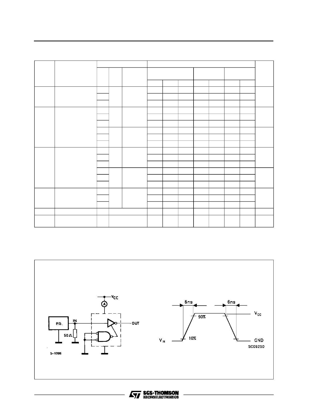
(*) CPD is defined as the value of the IC’s internal equivalent capacitance which is calculated from the operating current consumption without load.
(Refer to Test Circuit). Average operting current can be obtained by the following equation. ICC(opr) = CPD •VCC •fIN + ICC/8 (per gate)
TEST CIRCUIT ICC (Opr.)
HC540
6/12
Share Link: 