STGW38IH130D Просмотр технического описания (PDF) - STMicroelectronics
Номер в каталоге
Компоненты Описание
производитель
STGW38IH130D Datasheet PDF : 17 Pages
| |||
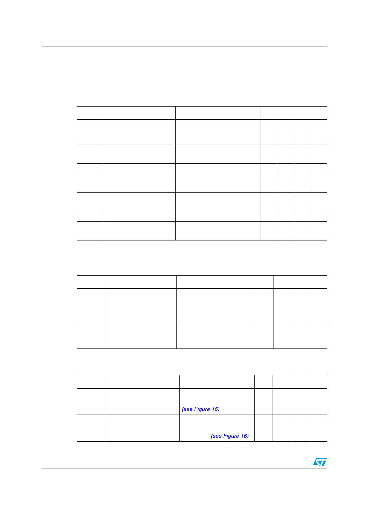
Electrical characteristics
2
Electrical characteristics
STGW38IH130D, STGWT38IH130D
TJ= 25 °C unless otherwise specified.
Table 4.
Symbol
Static
Parameter
Test conditions
Min. Typ. Max. Unit
Collector-emitter
V(BR)CES breakdown voltage
(VGE = 0)
IC = 1 mA
1300
V
VCE(sat)
Collector-emitter saturation VGE= 15 V, IC= 20 A
voltage
VGE= 15 V, IC= 20 A, TJ =125 °C
2.1 2.8 V
2.0
V
VGE(th) Gate threshold voltage
VCE= VGE, IC= 1 mA
3.75
5.75 V
ICES
Collector-cut-off current
(VGE = 0)
VCE =1300 V
VCE =1300 V, TJ=125 °C
1 mA
10 mA
IGES
gfs (1)
Gate-emitter leakage
current (VCE = 0)
VGE =± 20 V
Forward transconductance VCE = 25 V, IC= 20 A
±
100
nA
20
S
VF Diode forward voltage
IF = 20 A
IF = 20 A, TJ = 125 °C
1.9 V
1.3 1.7 V
1. Pulsed: pulse duration = 300 µs, duty cycle 1.5%
Table 5. Dynamic
Symbol
Parameter
Cies
Coes
Cres
Qg
Qge
Qgc
Input capacitance
Output capacitance
Reverse transfer
capacitance
Total gate charge
Gate-emitter charge
Gate-collector charge
Test conditions
Min. Typ. Max. Unit
2900
pF
VCE = 25 V, f = 1 MHz, VGE=0 -
155 -
pF
30
pF
VCE = 960 V,
IC= 20 A,VGE=15 V
127
nC
-
18 - nC
50
nC
Table 6. Inductive load switching times
Symbol
Parameter
Test conditions
tr(Voff)
td(off)
tf
tr(Voff)
td(off)
tf
Off voltage rise time
Turn-off delay time
Current fall time
Off voltage rise time
Turn-off delay time
Current fall time
VCC = 960 V, IC = 20 A
RG= 10 Ω, VGE= 15 V,
(see Figure 16)
VCC = 960 V, IC = 20 A
RG= 10 Ω, VGE= 15 V,
TJ= 125 °C (see Figure 16)
Min. Typ. Max. Unit
102
ns
- 284 - ns
180
ns
200
ns
- 424 - ns
316
ns
4/17
Doc ID 15697 Rev 4
Share Link: 