ZN428E8 Просмотр технического описания (PDF) - Unspecified
Номер в каталоге
Компоненты Описание
производитель
ZN428E8 Datasheet PDF : 9 Pages
| |||
ZN428
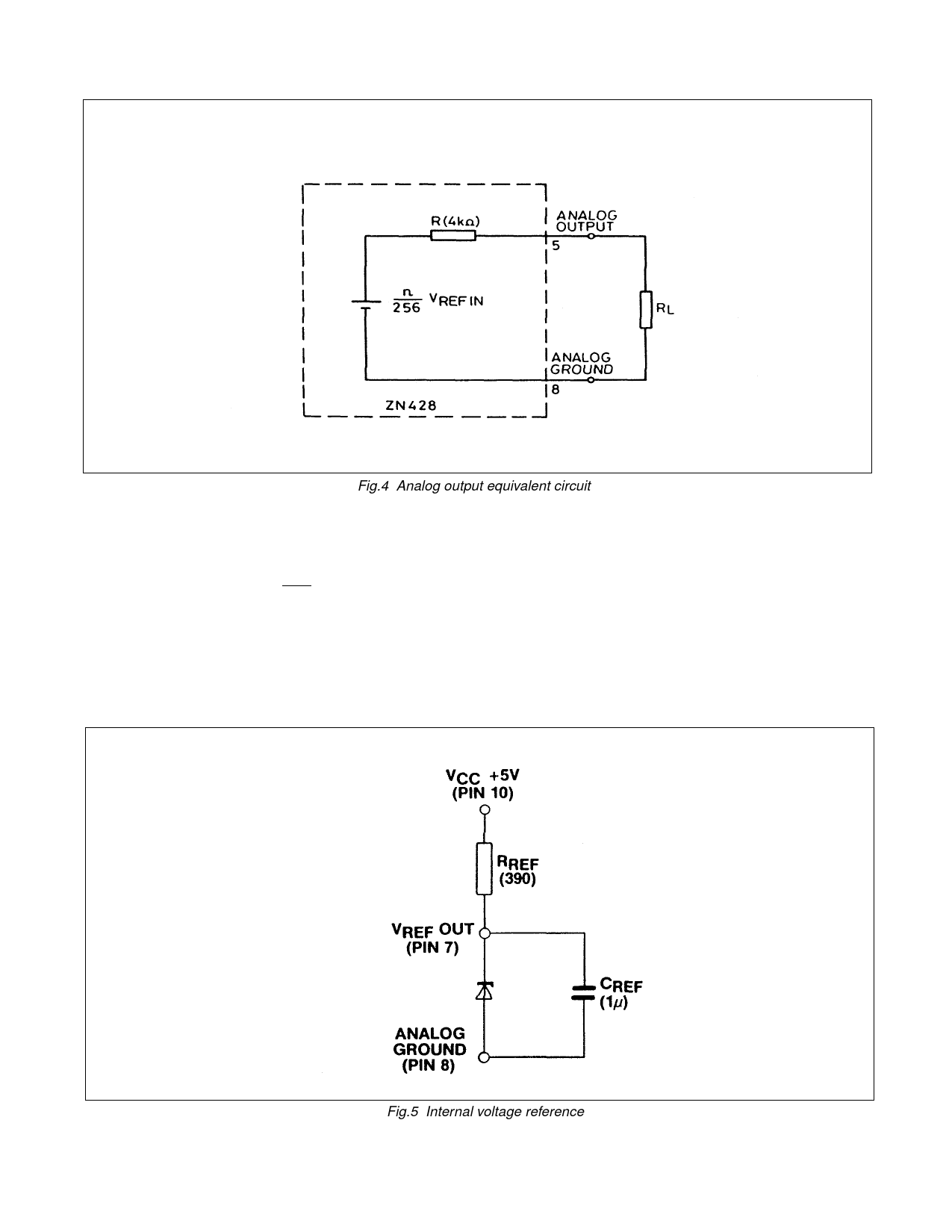
Fig.4 Analog output equivalent circuit
Fig.4 shows equivalent circuit of the output (ignoring
VOS). The output resistance R has a temperature coefficient
of +0.2% per °C.
The gain drift due to this is 0.2R % per °C.
R+RL
RL should be chosen as large as possible to make the
gain drift small. As an example if RL = 400kΩ then the gain
drift due to the T.C. of R for a 100°C change in ambient
temperature will be less than 0.2%. Alternatively the ZN428
can be buffered by an amplifier (see Operating Notes).
REFERENCE
(a) Internal Reference
The internal reference is an active bandgap circuit which
is equivalent to a 2.5V Zener diode with very low slope
impedance (Fig.5). A resistor (RREF), should be connected
between +VCC (pin 10) and pin 7. The recommended value
of 390Ω will supply a nominal reference current of (5.0-
2.5)/0.39 = 6.4mA. A stabilising/decoupling capacitor CREF =
1µF is required between pins 7 and 8 for internal reference
option, VREF OUT (pin 7) being connected to VREF IN (pin 6).
Fig.5 Internal voltage reference
Share Link: 