IR20153SPBF Просмотр технического описания (PDF) - International Rectifier
Номер в каталоге
Компоненты Описание
производитель
IR20153SPBF Datasheet PDF : 15 Pages
| |||
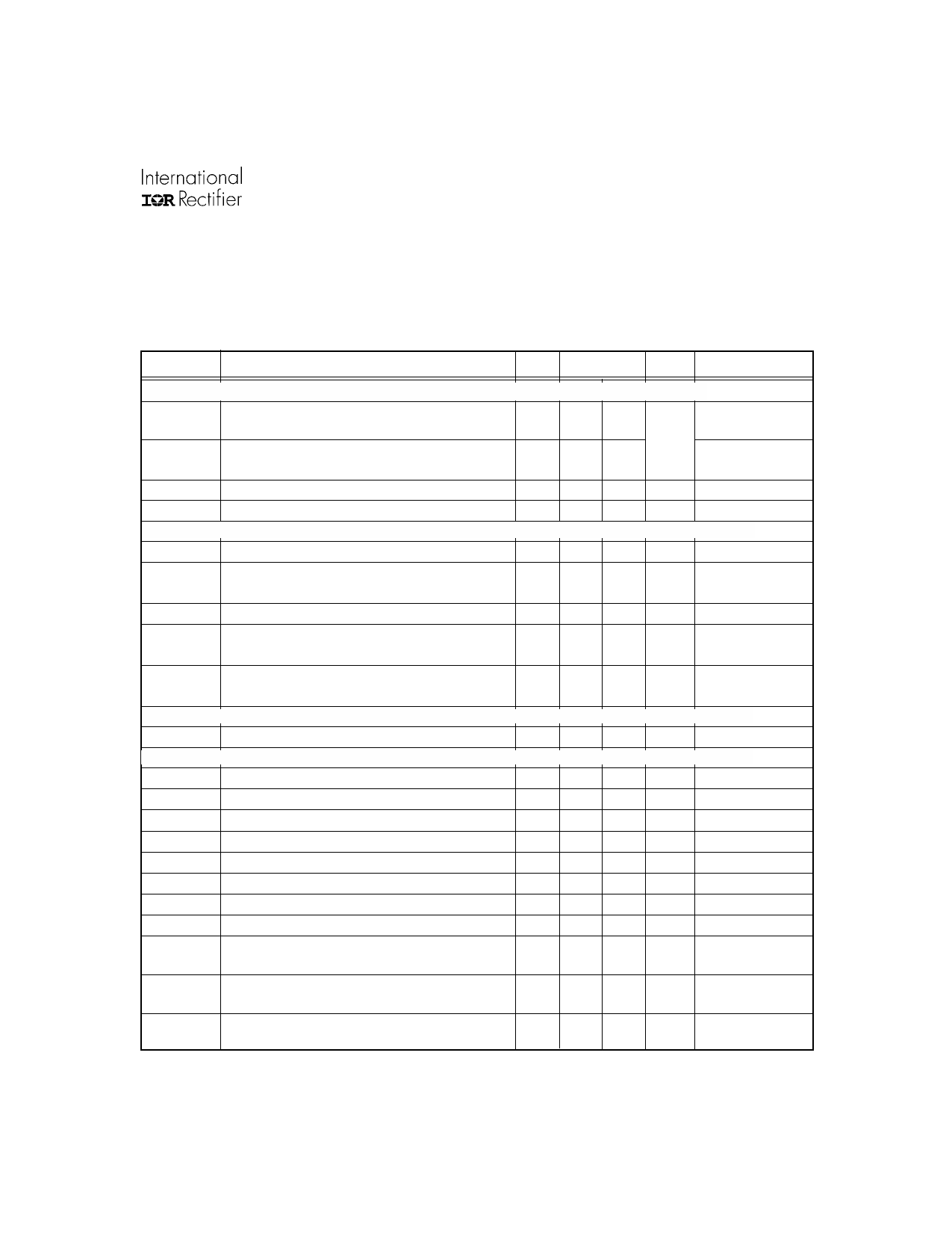
IR20153S & (PbF)
Electrical Characteristics
Unless otherwise specified, VCC = 5V, VBS = 7V, VS = 0V, IN = 0V, RES = 5V, load R = 50Ω, C = 6.8nF (see Figure 3).
Unless otherwise noted, these specifications apply for an operating ambient temperature of TA =25°C.
Symbol
Definition
VCC Supply Characteristics
VCCUV+
VCC supply undervoltage positive going threshold
Min.
—
VCCUV-
VCC supply undervoltage negative going threshold 2.5
VCCUVHYS VCC supply undervoltage lockout hysteresis
0.01
IQCC
VCC supply current
—
VBS Supply Characteristics
VBSUV+
VBS supply undervoltage positive going threshold
—
VBSUV- VBS supply undervoltage negative going threshold 2.5
VBSUVHYS VBS supply undervoltage lockout hysteresis
0.01
IQBS1
VBS supply current
—
IQBS2
VBS supply current
—
VB. VS Supply Characteristics
ILK
Offset supply leakage current
—
Gate Driver Characteristics
Io+1
Peak output source current
250
Io+2
Peak output source current
800
tr1
Output rise time
—
tr2
Output rise time
—
Io-1
Peak output sink current
250
Io-2
Peak output sink current
800
tf1
Output fall time
—
tf2
Output fall time
—
ton
Input-to-Output Turn-on propogation delay
—
(50% input level to 10% output level)
toff
Input-to-Output Turn-off propogation delay
—
(50% input level to 90% output level)
tres,off
RES-to-Output Turn-off propogation delay
—
(50% input level to 90% [tphl] output levels)
Typ. Max. Units Test Conditions
— 4.3
——
0.3 0.60
— 400
VCC rising from 0V
V
VCC dropping
from 5V
uA VCC = 3.6V & 6.5V
— 4.3
——
0.3 0.60
— 100
— 200
V VBS rising from 0V
VBS dropping
from 5V
µA static mode, VBS =
7V, IN = 0V or 5V
µA static mode, VBS =
16V, IN = 0V or 5V
—
50
µA
VB = VS = 150V
400 —
1500 —
0.2 0.4
0.1 0.2
400 —
1500 —
0.2 0.4
0.1 0.2
1.0 2.0
mA
mA
µsec
µsec
mA
mA
µsec
µsec
µsec
VBS = 16V
VBS = 16V
IN = 5V
VBS = 16V, IN = 5V
IN = 5V
VBS = 16V, IN = 5V
0.3 0.9 µsec
0.3 0.9 µsec
www.irf.com
3
Share Link: 