ADUM6400ARWZ(Rev0) Просмотр технического описания (PDF) - Analog Devices
Номер в каталоге
Компоненты Описание
производитель
ADUM6400ARWZ Datasheet PDF : 24 Pages
| |||
ADuM6400/ADuM6401/ADuM6402/ADuM6403/ADuM6404
ABSOLUTE MAXIMUM RATINGS
Ambient temperature = 25°C, unless otherwise noted.
Table 19.
Parameter
Storage Temperature Range (TST)
Ambient Operating Temperature
Range (TA)
Supply Voltages (VDD1, VISO)1
Input Voltage
(VIA, VIB, VIC, VID, VSEL)1, 2
Output Voltage
(VOA, VOB, VOC, VOD)1, 2
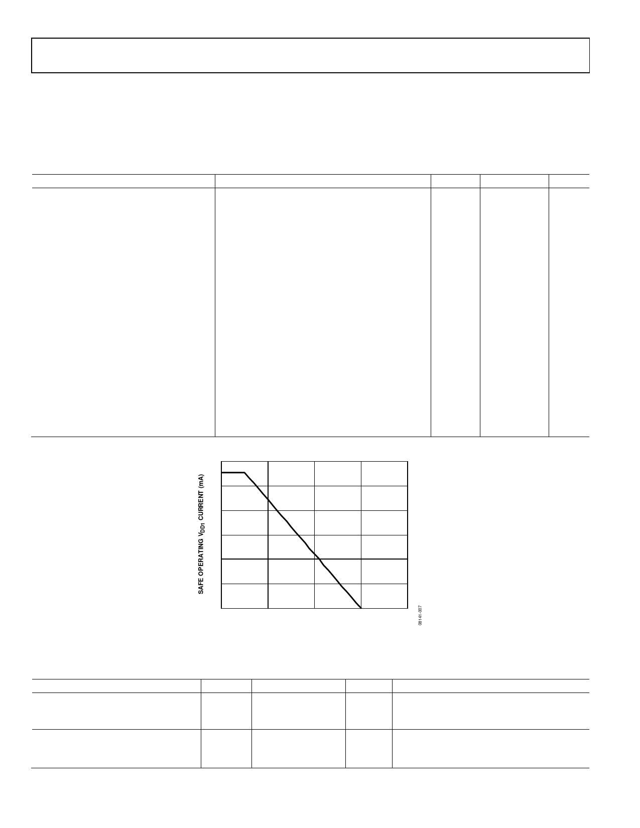
Average Output Current per Pin3
Common-Mode Transients4
Rating
−55°C to +150°C
−40°C to +105°C
−0.5 V to +7.0 V
−0.5 V to VDDI + 0.5 V
−0.5 V to VDDO + 0.5 V
−10 mA to +10 mA
−100 kV/μs to +100 kV/μs
1 Each voltage is relative to its respective ground.
2 VDDI and VDDO refer to the supply voltages on the input and output sides of a
given channel, respectively. See the Printed Circuit Board (PCB) Layout section.
3 See Figure 7 for maximum rated current values for various temperatures.
4. Common-mode transients exceeding the absolute maximum slew rate may
cause latch-up or permanent damage.
Stresses above those listed under Absolute Maximum Ratings
may cause permanent damage to the device. This is a stress
rating only; functional operation of the device at these or any
other conditions above those indicated in the operational
section of this specification is not implied. Exposure to absolute
maximum rating conditions for extended periods may affect
device reliability.
ESD CAUTION
Table 20. Maximum Continuous Working Voltage Supporting 50-Year Minimum Lifetime1
Parameter
Max
Unit
Applicable Certification
AC Voltage, Bipolar Waveform
424
V peak
All certifications, 50-year operation
AC Voltage, Unipolar Waveform
Basic Insulation
600
V peak
Working voltage per IEC 60950-1
Reinforced Insulation
560
V peak
Working voltage per DIN V VDE V 0884-10
DC Voltage
Basic Insulation
600
V peak
Working voltage per IEC 60950-1
Reinforced Insulation
560
V peak
Working voltage per DIN V VDE V 0884-10
1 Refers to the continuous voltage magnitude imposed across the isolation barrier. See the Insulation Lifetime section for more information.
Rev. 0 | Page 10 of 24
Share Link: 