ADT7310TRZ-REEL Просмотр технического описания (PDF) - Analog Devices
Номер в каталоге
Компоненты Описание
производитель
ADT7310TRZ-REEL Datasheet PDF : 25 Pages
| |||
Data Sheet
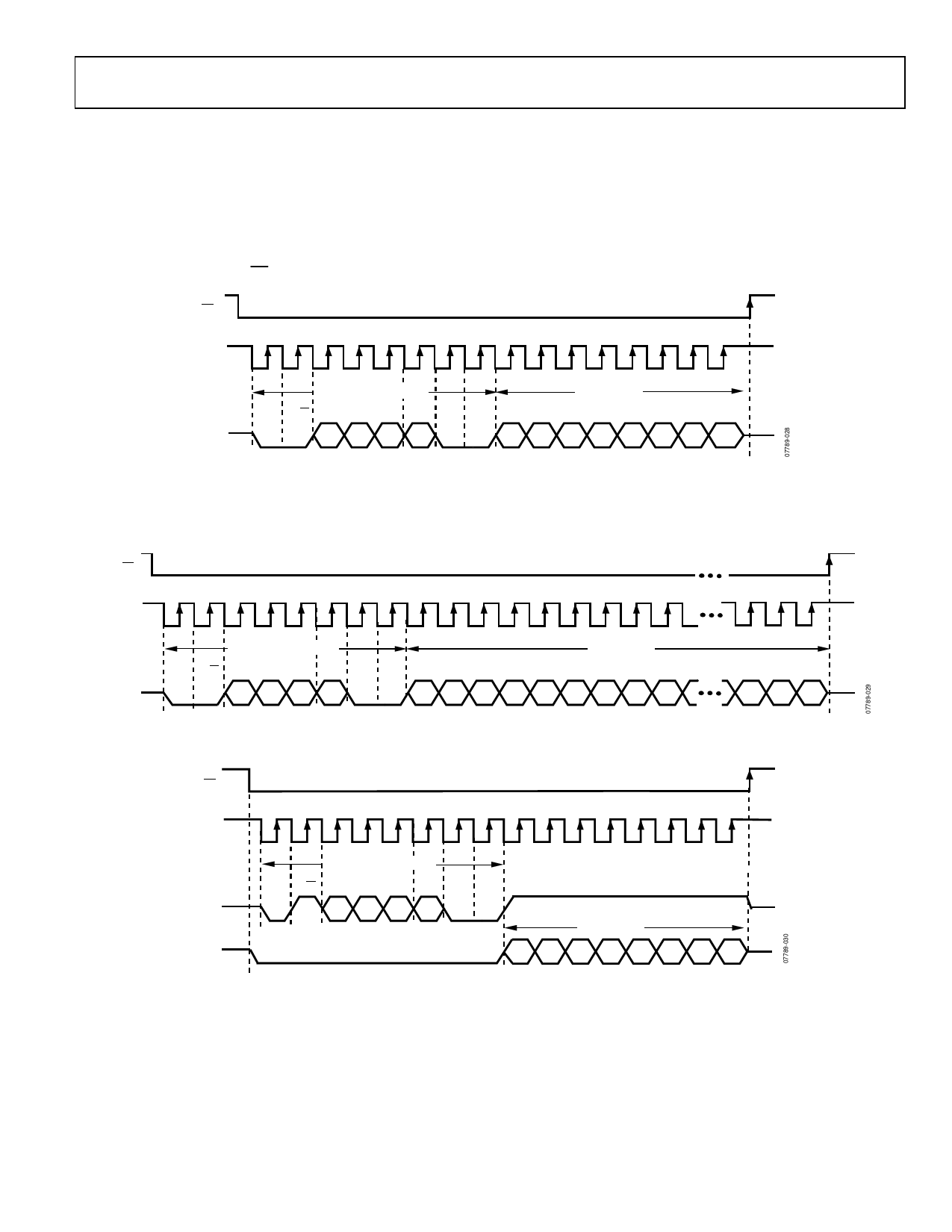
WRITING DATA
Data is written to the ADT7310 in eight bits or 16 bits, depending
on the addressed register. The first byte written to the device is
the command byte, with the read/write bit set to 0. The master
then supplies the 8-bit or 16-bit input data on the DIN line.
The ADT7310 clocks the data into the register addressed in
the command byte on the positive edge of SCLK. The master
finishes the write by pulling CS high.
CS
ADT7310
Figure 18 shows a write to an 8-bit register, and Figure 19 shows
a write to a 16-bit register.
The master must begin a new write transaction on the bus for
every register write. Only one register is written to per bus
transaction.
SCLK
DIN
1
2
3
4
5
6
7
8
9 10 11 12 13 14 15 16
8-BIT COMMAND BYTE
0
R/W
REGISTER ADDR
CONT
READ
0
0
8-BIT DATA
C7 C6 C5 C4 C3 C2 C1 C0 D7 D6 D5 D4 D3 D2 D1 D0
Figure 18. Writing to an 8-Bit Register
CS
SCLK
DIN
1
2
3
4
5
6
7
8
9 10 11 12 13 14 15 16 17
8-BIT COMMAND BYTE
0
R/W
REGISTER ADDR
CONT
READ
0
C7 C6 C5 C4 C3 C2 C1
16-BIT DATA
0
C0 D15 D14 D13 D12 D11 D10 D9 D8 D7
Figure 19. Writing to a 16-Bit Register
22 23 24
D2 D1 D0
CS
SCLK
DIN
DOUT
1
2
3
4
5
6
7
8
9 10 11 12 13 14 15 16
8-BIT COMMAND WORD
0
R/W
REGISTER ADDR
CONT
READ
0
0
C7 C6 C5 C4 C3 C2 C1 C0
8-BIT DATA
D7 D6 D5 D4 D3 D2 D1 D0
Figure 20. Read from an 8-Bit Register
Rev. A | Page 19 of 24
Share Link: 