TEA6846 Просмотр технического описания (PDF) - Philips Electronics
Номер в каталоге
Компоненты Описание
производитель
TEA6846 Datasheet PDF : 44 Pages
| |||
Philips Semiconductors
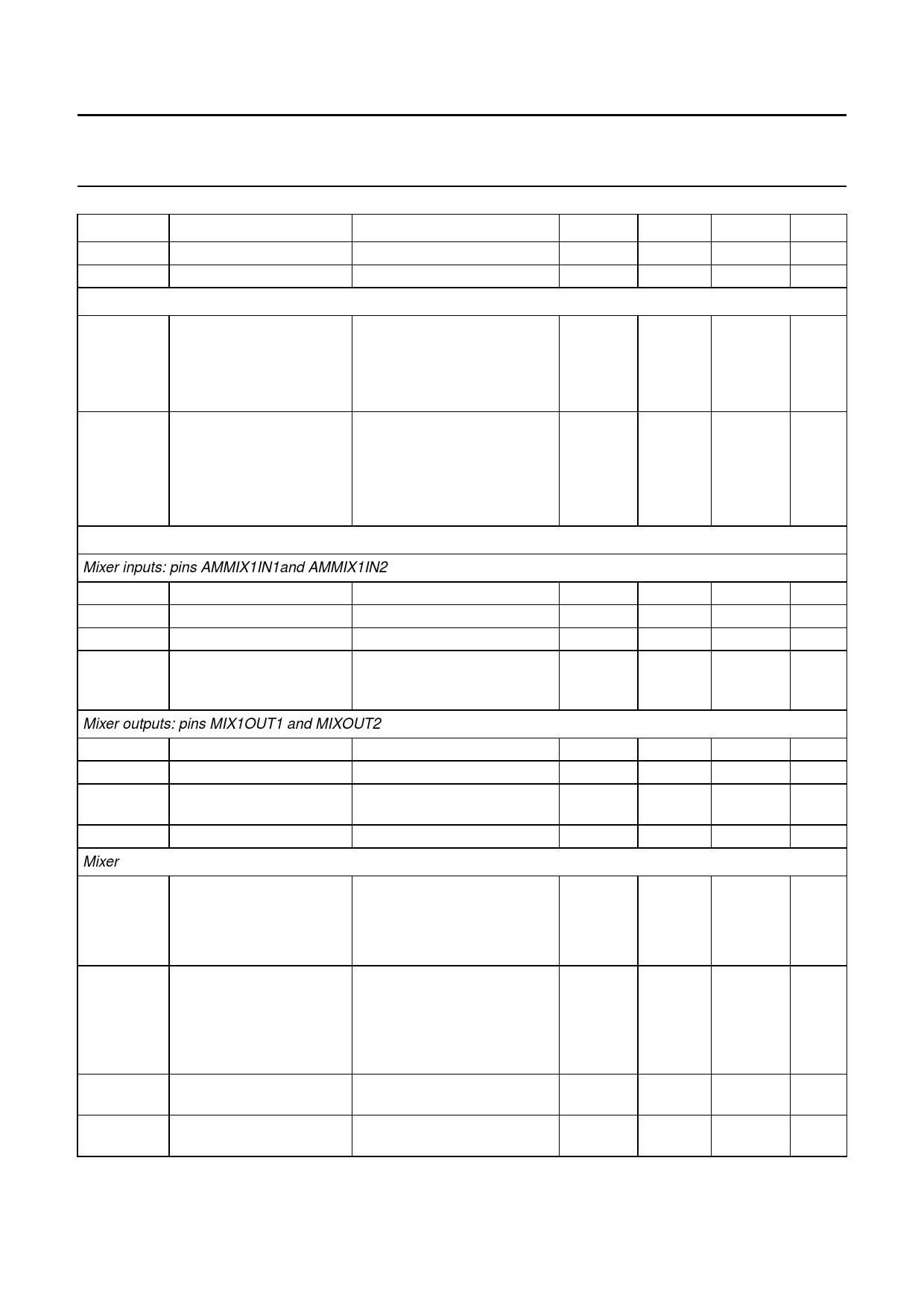
New In Car Entertainment (NICE) car radio
Product specification
TEA6846H
SYMBOL
PARAMETER
CONDITIONS
MIN.
Ro
output resistance
IIAMAGC = 1 µA
1
Co
output capacitance
−
AM RF AGC PEAK DETECTOR: PIN T2AMAGC
Iatt
attack current AGC peak
detector
Idec
decay current AGC peak
detector
AM MIXER 1 (IF1 = 10.7 MHZ)
data byte 5: bit 5 = 1,
−
bit 6 = 1;
AM mixer 1 input Vi = 1 V;
VT2AMAGC−GND = 3 V;
VAMIF2IN−AMIF2DEC = 0 V
data byte 5: bit 5 = 1,
−
bit 6 = 1;
AM mixer 1 input Vi = 0 V;
VT2AMAGC−AMMIN1IN2 = 0.25 V;
VT2AMAGC−GND = 3 V;
VAMIF2IN−AMIF2DEC = 0 V
Mixer inputs: pins AMMIX1IN1and AMMIX1IN2
Ri
Ci
VI
Vi(max)
input resistance
input capacitance
DC input voltage
maximum voltage on
pin AMMIX1IN1
note 4
50
note 4
−
2.3
1 dB compression point of 500
AM mixer 1 output
(peak-to-peak)
Mixer outputs: pins MIX1OUT1 and MIXOUT2
Ro
output resistance
note 5
100
Co
output capacitance
note 5
−
Vo(max)(p-p) maximum output voltage
12
(peak-to-peak value)
Ibias
mixer bias current
AM mode
4.8
Mixer
gm(conv)
gm(conv)(T)
IP3
IP2
conversion
2.0
transconductance
V-----F---M---M----II-X-M--I--NI-X--1-O--–--U--F-T--M-1--M----I-X---I--N---2-
conversion
−
transconductance
variation with temperature
g----m-∆---(-gc---o-m-n---(v-c-)-o--×-n--v--∆-)--T--
3rd-order intermodulation RL = 2.8 kΩ (AC load between 135
output pins)
2nd-order intermodulation RL = 2.8 kΩ (AC load between −
output pins)
TYP.
−
5
MAX.
−
7
3.15
−
2.6
−
70
100
5
7
2.7
3.1
−
−
−
−
5
7
15
−
6
7.2
2.55
3.2
−9 × 10⁻⁴ −
138
−
170
−
UNIT
MΩ
pF
mA
µA
kΩ
pF
V
mV
kΩ
pF
V
mA
m---V---A--
K−1
dBµV
dBµV
2001 Apr 12
16
Share Link: 