TDA9887TS Просмотр технического описания (PDF) - Philips Electronics
Номер в каталоге
Компоненты Описание
производитель
TDA9887TS
Philips Electronics
TDA9887TS Datasheet PDF : 58 Pages
| |||
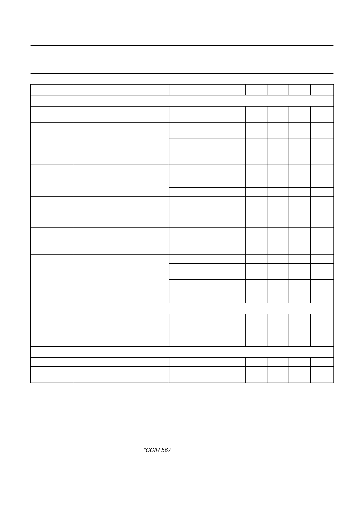
Philips Semiconductors
I2C-bus controlled multistandard alignment-free
IF-PLL demodulator with FM radio
Product specification
TDA9887
SYMBOL
PARAMETER
CONDITIONS
MIN. TYP. MAX. UNIT
Audio part
Vo(AF)(rms)
THD
BAF(−3dB)
S/NW(AF)
αAM(sup)
PSRRAUD
Vo(intc)(rms)
AF output voltage (RMS value)
total harmonic distortion of audio
signal
−3 dB AF bandwidth
weighted signal-to-noise ratio of
audio signal
AM suppression of
FM demodulator
power supply ripple rejection on
pin AUD
IF intercarrier output level
(RMS value)
27 kHz FM deviation;
430
50 µs de-emphasis
FM: 27 kHz FM deviation; −
50 µs de-emphasis
AM: m = 54 %
−
without de-emphasis;
80
dependent on FM-PLL filter
FM: 27 kHz FM deviation; 52
50 µs de-emphasis;
vision carrier unmodulated
AM: m = 54 %
45
50 µs de-emphasis;
40
AM: f = 1 kHz and
m = 54 %; referenced to
27 kHz FM deviation
fripple = 70 Hz; see Fig.6
for AM
20
for FM
14
QSS mode; SC1; SC2 off 90
L standard;
90
without modulation
intercarrier mode;
−
PC/SC1 = 20 dB; SC2 off;
note 6
540 650 mV
0.15 0.50 %
0.5 1.0 %
100 −
kHz
56
−
dB
50
−
dB
46
−
dB
26
−
dB
20
−
dB
140 180 mV
140 180 mV
75
−
mV
Radio part
AFCstps
Vi(FM)(rms)
AFC control steepness
IF intercarrier input level on
pin FMIN for gain controlled
operation of FM-PLL (RMS value)
definition: ∆IAFC/∆fRIF
0.85
radio mode and FM external 1
mode; see Table 16
1.05
−
1.25
100
µA/kHz
mV
Reference frequency
fref
Vref(rms)
reference signal frequency
reference signal voltage
(RMS value)
note 7
−
4
operation as input terminal 80
−
−
MHz
400 mV
Notes
1. Values of video and sound parameters can be decreased at VP = 4.5 V.
2. For applications without I2C-bus, the time constant (R × C) at the supply must be >1.2 µs (e.g. 1 Ω and 2.2 µF).
3. Condition: luminance range (5 steps) from 0 % to 100 %.
4. AC load: CL < 20 pF and RL > 1 kΩ. The sound carrier frequencies (depending on the TV standard) are attenuated
by the integrated sound carrier traps (see Figs 15 to 20; H (s) is the absolute value of transfer function).
5. S/NW is the ratio of the black-to-white amplitude to the black level noise voltage (RMS value measured on pin CVBS).
B = 5 MHz weighted in accordance with “CCIR 567”.
2004 Aug 25
5
Share Link: 