PI90LVB022 Просмотр технического описания (PDF) - Pericom Semiconductor
Номер в каталоге
Компоненты Описание
производитель
PI90LVB022 Datasheet PDF : 12 Pages
| |||
PI90LV022, PI90LVB022
LVDS Mux / Repeater 1122334455667788990011223344556677889900112233445566778899001122112233445566778899001122334455667788990011223344556677889900112211223344556677889900112233445566778899001122334455667788990011221122334455667788990011223344556677889900112233445566778899001122112233445566778899001122
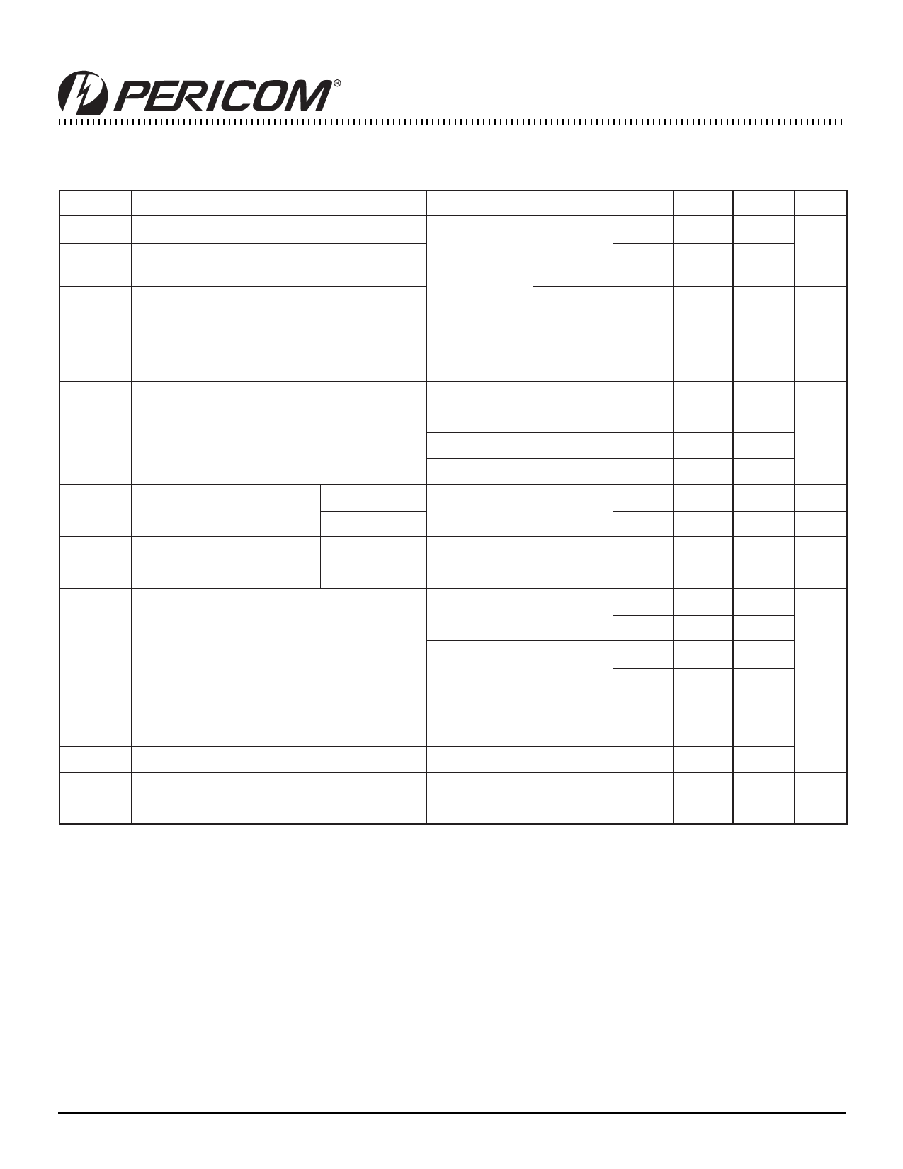
Receiver/Driver Electrical Characteristics Over Recommended Operating Conditions (unless otherwise noted)
Symbol
Parameter
Test Conditions
Min. Typ.(1) Max. Units
VOD
Differential output voltage magnitude
247
440
590
∆VOD
Change in differential output voltage magnitude RL = 100 Ohm See Fig. 3
between logic states
(LV022)
–50
mV
50
VOC(SS)
Steady-state common-mode output voltage
1.125
1.375 V
∆VOC(SS)
Change in steady-state common-mode output
voltage between logic states
RL = 50 Ohm
(LVB022)
See Fig. 4
–50
3
50
mV
VOC(PP) Peak-to-peak common-mode output voltage
150
No Load
8
12
ICC
Supply current
RL = 100 Ohm (LV022)
RL = 50 Ohm (LVB022)
13
20
mA
21
27
Both Channels Disabled
3
6
IH
High-level input current
DE
S0, S1
VIH = 5
40
nA
–3
µA
IIL
Low-level input current
DE
S0, S1
VIL = 0.8V
–20
nA
10
µA
IOS
Short-circuit output current
VOY or VOZ = 0V,
VOD = 0V (LV022)
VOY or VOZ = 0V,
VOD = 0V (LVB022)
–10
–10
mA
–10
–10
IOZ
IO(OFF)
CIN
High-Impedence output current
Power-off output current
Input capacitance
VOD = 600mV
VO = 0V or VCC
VCC = 0V, VO = 3.6V
S0, S1, 1DE, 2DE
1.5
±25
1.5
±25
nA
1.5
±40
3
pF
8
Note:
1. All typical values are at 25°C and with a 3.3 supply
5
PS8488B
09/28/04
Share Link: 