ST72254G2 Просмотр технического описания (PDF) - STMicroelectronics
Номер в каталоге
Компоненты Описание
производитель
ST72254G2
STMicroelectronics
ST72254G2 Datasheet PDF : 135 Pages
| |||
ST72104G, ST72215G, ST72216G, ST72254G
POWER SAVING MODES (Cont’d)
8.4 HALT MODE
The HALT mode is the lowest power consumption
mode of the MCU. It is entered by executing the
ST7 HALT instruction (see Figure 20).
The MCU can exit HALT mode on reception of ei-
ther a specific interrupt (see Table 5, “Interrupt
Mapping,” on page 26) or a RESET. When exiting
HALT mode by means of a RESET or an interrupt,
the oscillator is immediately turned on and the
4096 CPU cycle delay is used to stabilize the os-
cillator. After the start up delay, the CPU resumes
operation by servicing the interrupt or by fetching
the reset vector which woke it up (see Figure 19).
When entering HALT mode, the I bit in the CC reg-
ister is forced to 0 to enable interrupts. Therefore,
if an interrupt is pending, the MCU wakes immedi-
ately.
In the HALT mode the main oscillator is turned off
causing all internal processing to be stopped, in-
cluding the operation of the on-chip peripherals.
All peripherals are not clocked except the ones
which get their clock supply from another clock
generator (such as an external or auxiliary oscilla-
tor).
The compatibility of Watchdog operation with
HALT mode is configured by the “WDGHALT” op-
tion bit of the option byte. The HALT instruction
when executed while the Watchdog system is en-
abled, can generate a Watchdog RESET (see
Section 15.1 ”OPTION BYTES” on page 129 for
more details).
Figure 19. HALT Mode Timing Overview
RUN
HALT
4096 CPU CYCLE
DELAY
RUN
HALT
IN STRU CTIO N
RESET
OR
INTERRUPT
FETCH
VECTO R
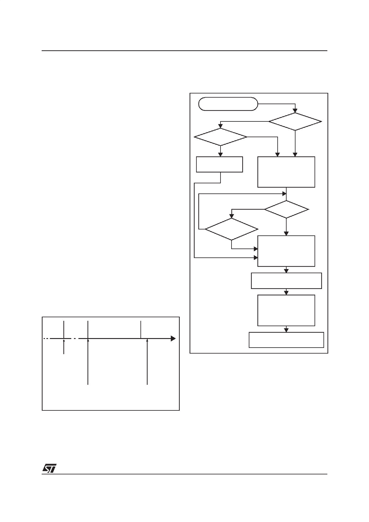
Figure 20. HALT Mode Flow-chart
HALT INSTRUCTION
WDGHALT 1)
1
WATCHDOG
RESET
ENABLE
0
WAT CHDOG
DISABLE
OSCILLATOR OFF
PERIPHERALS 2) OFF
CPU
OFF
I BIT
0
N
RESET
N
Y
INTERRUPT 3)
Y
OSCILLATOR ON
PERIPHERALS OFF
CPU
ON
I BIT
1
4096 CPU CLOCK CYCLE
DELAY
OSCILLATOR ON
PERIPHERALS ON
CPU
ON
I BIT
X 4)
FETCH RESET VECTOR
OR SERVICE INTERRUPT
Notes:
1. WDGHALT is an option bit. See option byte sec-
tion for more details.
2. Peripheral clocked with an external clock source
can still be active.
3. Only some specific interrupts can exit the MCU
from HALT mode (such as external interrupt). Re-
fer to Table 5, “Interrupt Mapping,” on page 26 for
more details.
4. Before servicing an interrupt, the CC register is
pushed on the stack. The I bit of the CC register is
set during the interrupt routine and cleared when
the CC register is popped.
29/135
Share Link: 