NJM2512A Просмотр технического описания (PDF) - Japan Radio Corporation
Номер в каталоге
Компоненты Описание
производитель
NJM2512A Datasheet PDF : 6 Pages
| |||
NJM2512A
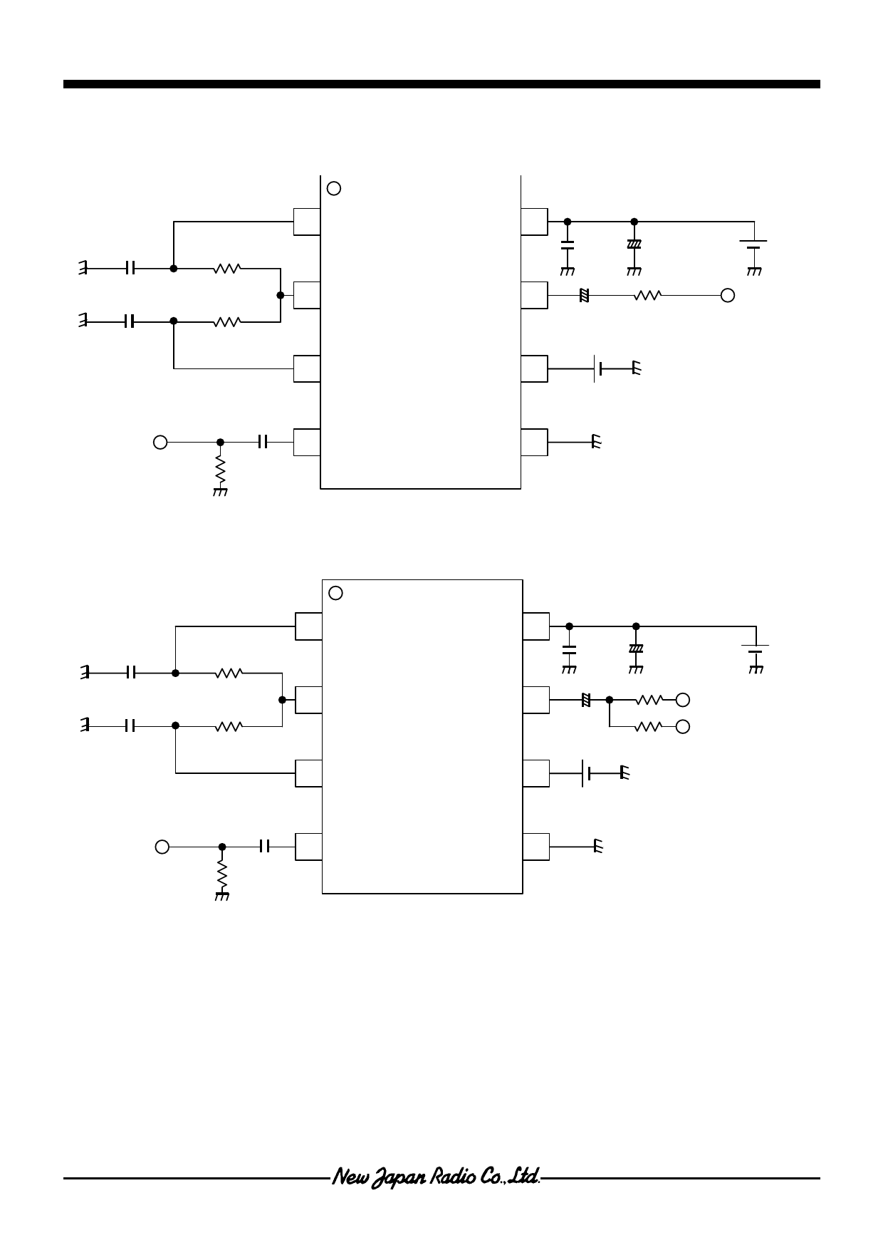
Q APPLICATION CIRCUIT1
1 SSIGV
V+ 8
0.1µF + 47µF
V+
0.1µF
1µF
68kΩ
68kΩ
2 VSAG
3 SREFV
VOUT 7
+
47µF 75Ω
PS 6
4 VIN
75Ω 0.1µF
GND 5
Q APPLICATION CIRCUIT2(2-line drive)
1 SSIGV
0.1u
36kΩ
2 VSAG
1u
36kΩ
3 SREFV
VCC 8
VOUT 7
PS 6
0.1u + 47u
+
75Ω
47u
75Ω
VCC
4 VIN
75Ω
0.1u
GND 5
QAPPLICATION NOTE
NJM2512 Ahas possibilities that decrease in the capacitance in low-frequency band when the ceramic capacitor is
used(pin7). It is a possibility that the sag is generated when the ceramic capacitor decreases capacity.
Please verify it in consideration of the capacity drop of the ceramic capacitor.
Ver.1
-4-
Share Link: 