MMAD1108E3 Просмотр технического описания (PDF) - Microsemi Corporation
Номер в каталоге
Компоненты Описание
производитель
MMAD1108E3 Datasheet PDF : 2 Pages
| |||
SCOTTSDALE DIVISION
MMAD1108 and MMAD1108e3
Switching Diode Array Steering Diode
TVS Array™
Symbol
VBR
VRWM
VF
IR
C
SYMBOLS & DEFINITIONS
Definition
Minimum Breakdown Voltage: The minimum voltage the device will exhibit at a specified current.
Working Peak Reverse Voltage: The maximum peak voltage that can be applied over the operating
temperature range.
Maximum Forward Voltage: The maximum forward voltage the device will exhibit at a specified current.
Maximum Leakage Current: The maximum leakage current that will flow at the specified voltage and
temperature.
Capacitance: The capacitance of the TVS as defined @ 0 volts at a frequency of 1 MHz and stated in
picofarads.
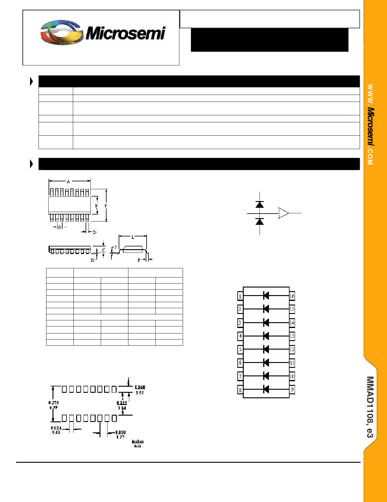
OUTLINE AND CIRCUIT
Supply rail (+VCC)
I/O Port
DIM
A
B
C
D
F
G
J
K
L
P
INCHES
MIN
MAX
0.358
0.398
0.150
0.158
0.053
0.069
0.011
0.021
0.016
0.050
0.050 BSC
0.006
0.010
0.004
0.008
0.189
0.228
0.206
0.244
MILLIMETERS
MIN
MAX
9.09
10.10
3.81
4.01
1.34
1.75
0.28
0.53
0.41
1.27
01.27 BSC
0.15
0.25
0.10
0.20
4.80
5.23
5.79
6.19
OUTLINE
GND (or -VCC)
STEERING DIODE APPLICATION
figure 1
CIRCUIT CONFIGURATION
PAD LAYOUT
Copyright © 2005
6-28-2005 REV L
Microsemi
Scottsdale Division
8700 E. Thomas Rd. PO Box 1390, Scottsdale, AZ 85252 USA, (480) 941-6300, Fax: (480) 947-1503
Page 2
Share Link: 