LB1851M Просмотр технического описания (PDF) - SANYO -> Panasonic
Номер в каталоге
Компоненты Описание
производитель
LB1851M Datasheet PDF : 6 Pages
| |||
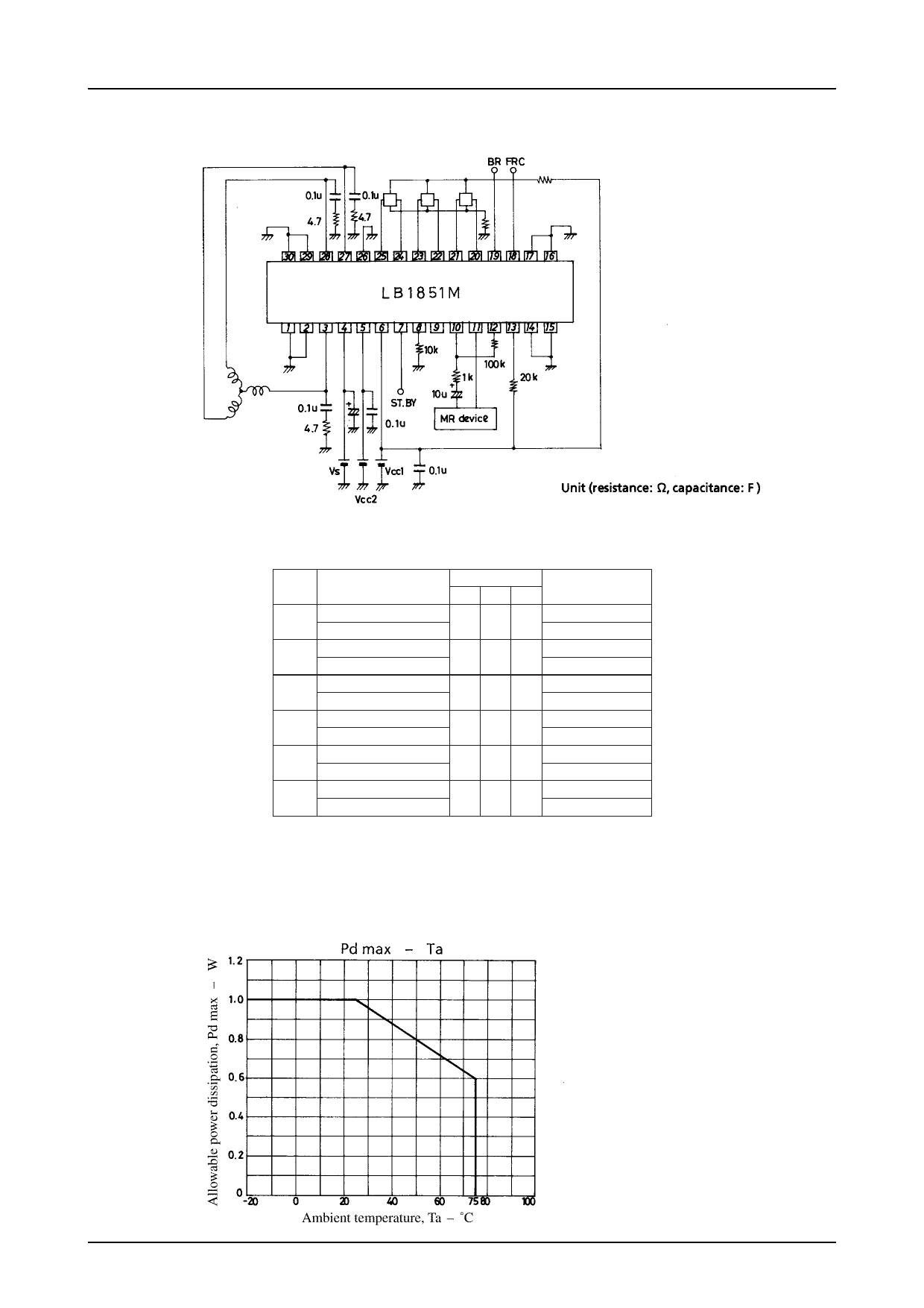
Sample Application Circuit
LB1851M
Truth Table
Mode Source
Input
Sink U V W
W phase→ V phase
1
HH L
V phase→ W phase
W phase→ U phase
2
HL L
U phase→ W phase
V phase→ W phase
3
L LH
W phase→ V phase
U phase→ V phase
4
LHL
V phase→ U phase
V phase→ U phase
5
HLH
U phase→ V phase
U phase→ W phase
6
L HH
W phase→ U phase
Forward/Reverse
Control
L
H
L
H
L
H
L
H
L
H
L
H
Input : “H” : Input 1 of each phase is at a potential which is higher by more than 0.2V relative to input 2.
“L” : Input 1 of each phase is at a potential which is lower by more than 0.2V relative to input 2.
Forward/reverse control : “H” :2.8V to VCC1
“L” : 0V to 1.2V
No.3659-4/6
Share Link: 