API9221 Просмотр технического описания (PDF) - Diodes Incorporated.
Номер в каталоге
Компоненты Описание
производитель
API9221
Diodes Incorporated.
API9221 Datasheet PDF : 16 Pages
| |||
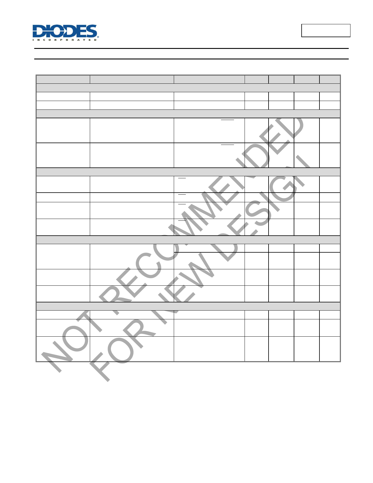
API9221
Electrical Characteristics
API9221 is tested at VDC = VUSB = 5V at an ambient temperature of +25°C unless otherwise noted.
Symbol
Parameter
Test Conditions
Min
Typ.
CHARGER POWER-ON THRESHOLDS
VPOR
Rising VUSB/VDC Threshold -
3.4
3.9
VPOF
Falling VUSB/VDC Threshold -
3.2
3.7
INPUT VOLTAGE OFFSET
VOSHC
Rising VDC or VUSB, relative
to VBAT
VBAT = 4.0V, use CHG
pin to indicate the
comparator output
-
150
VOSLC
Falling VDC or VUSB, relative VBAT = 4.0V, use CHG
to VBAT
pin to indicate the
comparator output
20
80
STANDBY CURRENT
ISTANDBY
BAT Pin Sink Current
EN = HIGH or both inputs
-
0.05
are floating
IVDC
IVUSB
VDC Pin Supply Current
VUSB Pin Supply Current
EN = HIGH, ILDO = 0
EN = HIGH, USB_BYP
disconnected
-
380
-
330
IVDC_VUSB
VDC/VUSB Pin Supply Current EN = LOW, ILDO = 0,
-
0.63
USB_BYP disconnected
VOLTAGE REGULATION
Load = 10mA
4.158 4.2
VBATMAX
Final Output Voltage, BAT Pin
Load = 10mA
(TJ = +25°C)
4.174 4.2
RDS(ON)_VDC
VDC Linear ON-resistance
VBAT =3.8V, IVDC = 0.3A,
(TJ = +25°C)
-
550
RDS(ON)_VUSB
VUSB Linear ON-resistance
VBAT = 3.8V, IUSB = 0.3A,
(TJ = +25°C)
-
550
CHARGE CURRENT
VIVDC
IVDC_CHRG
IVDC_TRKL
VDC Pin Output Voltage
VDC Constant Current
VDC Trickle Charge Current
VBAT = 3.8V
RIVDC = 12.4kΩ,
VBAT = 2.7V to 3.8V
RIVDC = 12.4kΩ,
VBAT = 2.2V, given as a %
of the IVDC_CHARGE
1.22
450
15
1.25
550
17
Max Unit
4.2
V
4.0
V
250
mV
-
mV
0.5
µA
460
µA
400
µA
1.1
mA
4.242
V
4.226
V
-
mΩ
-
mΩ
1.28
V
600
mA
19
%
API9221
Document number: DS32204 Rev. 3 - 3
5 of 16
www.diodes.com
June 2016
© Diodes Incorporated
Share Link: 