74ACTQ541 Просмотр технического описания (PDF) - Fairchild Semiconductor
Номер в каталоге
Компоненты Описание
производитель
74ACTQ541 Datasheet PDF : 9 Pages
| |||
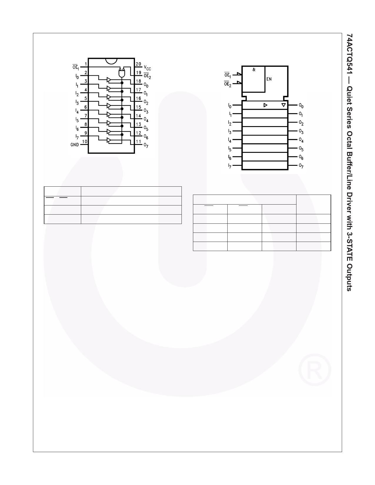
Connection Diagram
Logic Symbol
IEEE/IEC
Pin Description
Pin Name
OE1–OE2
I0–I7
O1–O7
Pin Description
3-STATE Output Enable (Active-LOW)
Inputs
Outputs
Truth Table
OE1
L
H
X
L
Inputs
OE2
L
X
H
L
H = HIGH Voltage Level
L = LOW Voltage Level
X = Immaterial
Z = High Impedance
I
Outputs
H
H
X
Z
X
Z
L
L
©1993 Fairchild Semiconductor Corporation
74ACTQ541 Rev. 1.6.0
2
www.fairchildsemi.com
Share Link: 