MAX1928 Просмотр технического описания (PDF) - Maxim Integrated
Номер в каталоге
Компоненты Описание
производитель
MAX1928 Datasheet PDF : 12 Pages
| |||
Low-Output-Voltage, 800mA, PWM Step-Down
DC-DC Converters
Pin Description
PIN
NAME
FUNCTION
1
PWM Forced-PWM Input. Drive to GND to use PWM at medium to heavy loads and pulse-skipping at light loads.
Drive to BATT to force PWM operation at all loads.
2
GND Ground
3
REF Internal 1.25V Reference. Bypass to GND with a 0.1µF capacitor.
Output Feedback Sense Input. To set the output voltage to the preset voltage (MAX1928), connect FB directly
4
FB to the output. To adjust the output voltage (MAX1927R), connect FB to the center of an external resistor-
divider between the output and GND. FB regulation voltage is 0.75V.
5
COMP
Compensation Input. See the Compensation, Stability, and Output Capacitor section for compensation
component selection.
6
SHDN Shutdown Control Input. Drive low to shut down the converter. Drive high for normal operation.
7
PGND Power Ground
8
LX Inductor Connection to the drains of the internal power MOSFETs.
9
BATT Supply Voltage Input. Connect to a 2.6V to 5.5V source. Bypass to GND with a low-ESR 10µF capacitor.
10
POK
Power-OK Open-Drain Output. Once the soft-start routine has completed, POK goes high impedance 20ms
after FB exceeds 90% of its expected final value.
COMP
SLOPE
COMPENSATION
PWM
COMPARATOR
MAX1927
MAX1928
BATT
BIAS
P
P
LX
1MHz
OSC
PFM CURRENT
COMPARATOR
PWM
PWM
CONTROL
SHDN
TO
COMP
REF
1.25V
REFERENCE
ILIM
COMPARATOR
N
N-CHANNEL
CURRENT COMPARATOR
N
PGND
MAX1927R
ONLY
POWER-OK
POK
CONTROL
FB
MAX1928
ONLY
GND
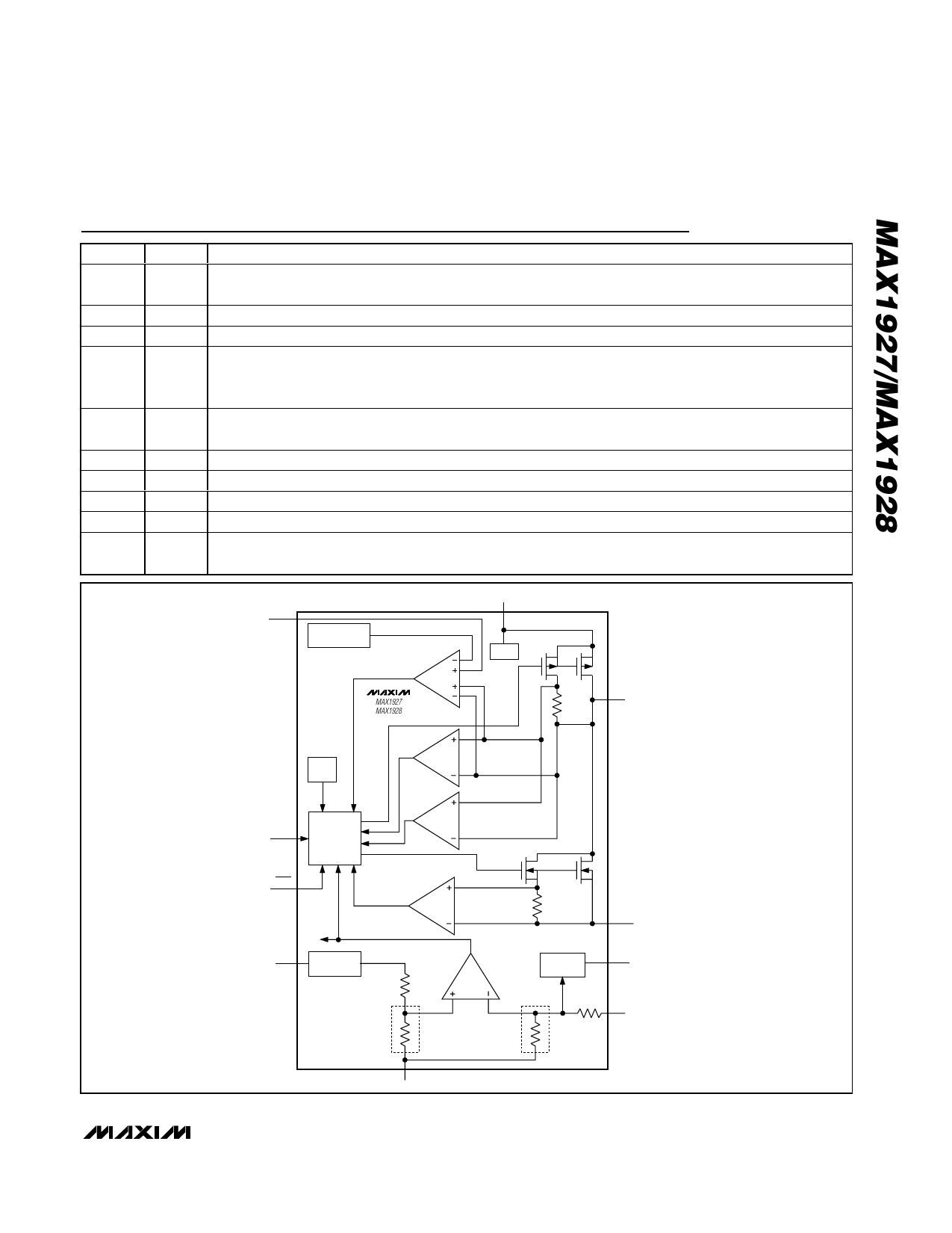
Figure 1. Simplified Functional Diagram
_______________________________________________________________________________________ 7
Share Link: 