MAX1921 Просмотр технического описания (PDF) - Maxim Integrated
Номер в каталоге
Компоненты Описание
производитель
MAX1921 Datasheet PDF : 12 Pages
| |||
MAX1920/MAX1921
Low-Voltage, 400mA Step-Down
DC-DC Converters in SOT23
Absolute Maximum Ratings
IN, FB, SHDN to AGND............................................-0.3V to +6V
OUT to AGND, LX to PGND.........................-0.3V to (IN + 0.3V)
AGND to PGND.....................................................-0.3V to +0.3V
OUT Short Circuit to GND...................................................... 10s
Continuous Power Dissipation (TA = +70°C)
6-Pin SOT23-6 (derate 8.7mW/°C above +70°C)........695mW
6-Pin TDFN (derate 18.2mW/°C above +70°C)......1454.5mW
Operating Temperature Range............................ -40°C to +85°C
Junction Temperature.......................................................+150°C
Storage Temperature......................................... -65°C to +150°C
Lead Temperature (soldering, 10s).................................. +300°C
Stresses beyond those listed under “Absolute Maximum Ratings” may cause permanent damage to the device. These are stress ratings only, and functional operation of the device at these
or any other conditions beyond those indicated in the operational sections of the specifications is not implied. Exposure to absolute maximum rating conditions for extended periods may affect
device reliability.
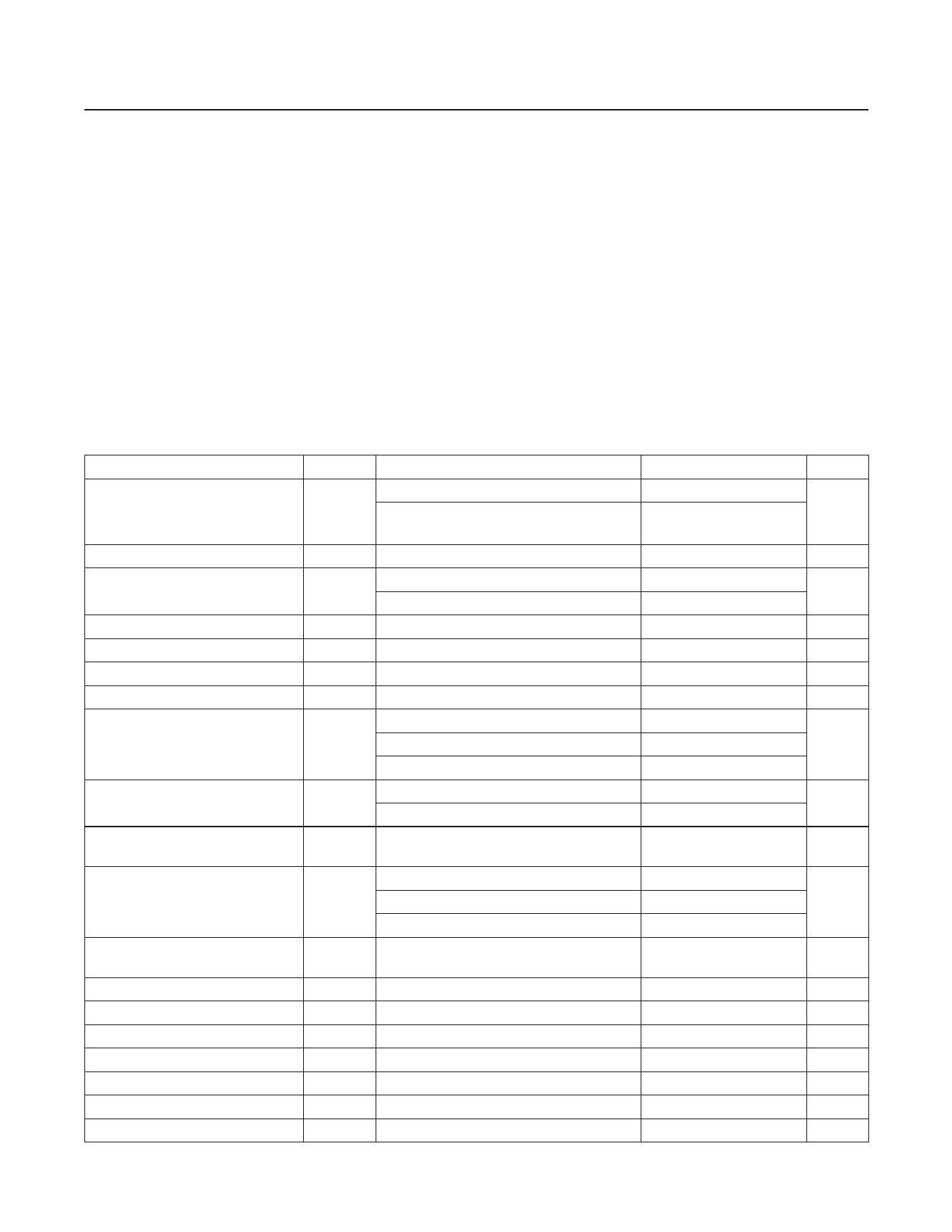
Electrical Characteristics
(VIN = 3.6V, SHDN = IN, TA = 0°C to +85°C. Typical parameters are at TA = +25°C, unless otherwise noted.) (Note 1)
PARAMETER
Input Voltage Range
Startup Voltage
UVLO Threshold
UVLO Hysteresis
Quiescent Supply Current
Quiescent Supply Current Dropout
Shutdown Supply Current
Output Voltage Accuracy
(MAX1921)
OUT BIAS Current
Output Voltage Range
(MAX1920)
FB Feedback Threshold
(MAX1920)
FB Feedback Hysteresis
(MAX1920)
FB Bias Current (MAX1920)
Load Regulation
Line Regulation
SHDN Input Voltage High
SHDN Input Voltage Low
SHDN Leakage Current
High-Side Current Limit
SYMBOL
CONDITIONS
I(LX) < 400mA
VIN I(LX) < 200mA
(MAX1921EUT15, MAX1921EUT18)
UVLO
VIN rising
VIN falling
IIN
IIN
ISHDN
IOUT
No switching, no load
SHDN = IN, OUT/FB = 0
SHDN = GND
IOUT = 0, TA = +25°C
IOUT = 0 to 400mA, TA = -40°C to +85°C
IOUT = 0 to 200mA, TA = -40°C to +85°C
SHDN = 0
OUT at regulation voltage
Figure 4, IN = 4.5V
VFB
VHYS
IFB
VIH
VIL
ISHDN
ILIMP
TA = +25°C
TA = -40°C to +85°C
FB = 1.5V
IOUT = 0 to 400mA
VIN = 2.5V to 5.5V
SHDN = GND or IN
MIN TYP MAX UNITS
2.5
5.5
V
2.0
2.5
2.0
V
1.85 1.95
V
1.50 1.65
200
mV
50
70
µA
220
300
µA
0.1
4.0
µA
-1.5
+1.5
-3
+3
%
-3
+3
1
µA
8
16
1.25
4.00
V
1.231 1.25 1.269
1.220 1.25 1.280
V
1.210
1.280
5
mV
0.01 0.20
µA
0.005
%/mA
0.2
%/V
1.6
V
0.4
V
0.001 1.000
µA
525
730
950
mA
www.maximintegrated.com
Maxim Integrated │ 2
Share Link: 