SSD1820A Просмотр технического описания (PDF) - Solomon Systech
Номер в каталоге
Компоненты Описание
производитель
SSD1820A Datasheet PDF : 43 Pages
| |||
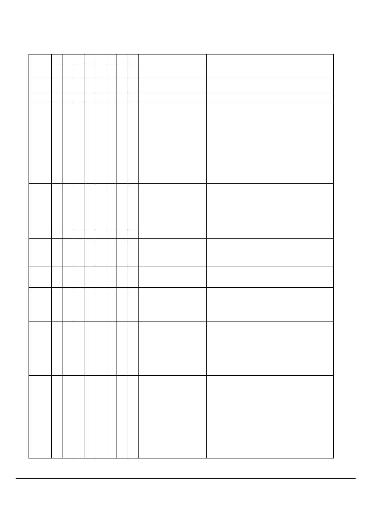
COMMAND TABLE
Hex
D7 D6 D5 D4 D3 D2 D1 D0 Command
Comment
00~0F 0 0 0 0 C3 C2 C1 C0 Set Lower Column Address Sets the lower nibble of the column address pointer for
RAM access. The pointer is reset to 0 after reset.
10~17 0 0 0 1 0 C6 C5 C4 Set Upper Column Address Sets the upper nibble of the column address pointer for
RAM access. The pointer is reset to 0 after reset.
18~1F
Reserved
Reserved
20~27 0 0 1 0 0 R2 R1 R0 Set Internal Regulator Resis- The internal regulator gain (1+R2/R1)Vcon increases as
tor Ratio
R2R1R0 is increased from 000b to 111b. The resistor
ratio (1+R2/R1) is given by:
R2R1R0 = 000: 2.3 (POR)
R2R1R0 = 001: 3.0
R2R1R0 = 010: 3.7
R2R1R0 = 011: 4.4
R2R1R0 = 100: 5.1
R2R1R0 = 101: 5.8
R2R1R0 = 110: 6.5
R2R1R0 = 111: 7.2
28~2F 0 0 1 0 1 VC VR VF Set Power Control Register VC=0: turns OFF the internal voltage booster (POR)
VC=1: turns ON the internal voltage booster
VR=0: turns OFF the internal regulator (POR)
VR=1: turns ON the internal regulator
VF=0: turns OFF the output op-amp buffer (POR)
VF=1: turns ON the output op-amp buffer
30~3F
Reserved
Reserved
40~43 0 1 0 0 0 0 x x Set Display Start Line
x L6 L5 L4 L3 L2 L1 L0
The next command specifies the row address pointer
(0-63) of the RAM data to be displayed in COM0. This
command has no effect on COMS. The pointer is set to
0 after reset.
44~47 0 1 0 0 0 1 x x Set Display Offset
x C6 C5 C4 C3 C2 C1 C0
The next command specifies the mapping of first display
line (COM0) to one of ROW0~63. This command has no
effect on COMS. COM0 is mapped to ROW0 after reset.
48~4B 0 1 0 0 1 0 x x Set Multiplex Ratio
x D6 D5 D4 D3 D2 D1 D0
The next command specifies the number of lines,
excluding COMS, to be displayed. With Icon is disabled
(POR), duties 1/16~1/64 or 1/80 could be selected. With
Icon enabled, the available duty ratios are 1/17~ 1/65 or
1/81.
4C~4F 0 1 0 0 1 1 x x Set N-line Inversion
x x x N4 N3 N2 N1 N0
The next command sets the n-line inversion register
from 3 to 33 lines to reduce display crosstalk. Register
values from 00001b to 11111b are mapped to 3 lines to
33 lines respectively. Value 00000b disables the N-line
inversion, which is the POR value.
To avoid a fix polarity at some lines, it should be noted
that the total number of mux (including the icon line)
should NOT be a multiple of the lines of inversion (n).
50~57 0 1 0 1 0 B2 B1 B 0 Set LCD Bias
Sets the LCD bias from 1/4 ~ 1/10 according to
B2B1B0:
000: 1/4 bias
001: 1/5 bias
010: 1/6 bias
011: 1/7bias
100: 1/8 bias
101: 1/9 bias (POR for SSD1820A)
110: 1/9 bias (for SSD1820A)
1/10 bias (POR for SSD1821)
111: 1/9 bias (for SSD1820A); 1/10 bias (for SSD1821)
SSD1820A/21 REV 1.4
18
01/03
SOLOMON
Share Link: 